Ren-T Assembly Instructions: Difference between revisions
Phil Short (talk | contribs) |
|||
| (9 intermediate revisions by 3 users not shown) | |||
| Line 1: | Line 1: | ||
== | ==The Board== | ||
[[Image:Ren-T (Top).jpg]] | |||
[[Image:Ren-T (dwg).gif]] | |||
<br> | |||
===Board Versions=== | |||
*V2.4 - Has provisions for mounting a dual secondary transformer. The dual secondary type transformer was later found to be undesirable for generating the Zero Crossing signal. | |||
*V2.5 - Removed D5 & D6 and pads for the dual secondary transformer | |||
== | ==Board Functions== | ||
The Renard Transformer (Ren-T) board has three basic functions: | |||
:# Generate a Zero Crossing (ZC) signal | |||
:# Convert the RS232 data coming from the computer to RS485 data | |||
:# Provide a voltage that the Renard 8 can use to generate it’s own operating voltage. | |||
<br> | |||
==Schematic Diagram== | |||
[[Image: Ren-T V25 Schematic.jpg | 800px]] | |||
<br> | |||
==Configurations== | |||
The Ren-T can be built in three basic configurations. How the Ren-T will be used with other devices will dictate which configuration that should be used. | |||
=== | ==='''CASE 1:''' === | ||
'''''Connecting PC to first controller without converting to RS485''''' | '''''Connecting PC to first controller without converting to RS485''''' | ||
<br> <br> | |||
[[Image: Ren-T Case 1.gif]] | |||
<br> | |||
In this configuration: | |||
*The RS232 data coming from the computer is not converted on the Ren-T. By placing the shunts on J1 and J2, the incoming RS232 data on P1 pin 3 is routed to JR1 pin 4. Also, GND on P1 pin 5 is routed to JR1 pin 5. | |||
*The transformer output is applied to diodes D1 & D2 to generate the ZC signal that is applied to JR1 pins 7 & 8. | |||
*Ren-T is connected to the serial port or a USB-to-Serial adapter on the controlling computer | |||
<br> | |||
This configuration is fine in situations where the computer, Ren-T and controller board are all in relative close proximity. RS232 data lines are usually only good for distances up to about 50 feet. | |||
=== | <br> | ||
'''''Connecting one Controller to the next (RS485 pass-through) ''''' | ---- | ||
<br> | |||
==='''CASE 2:''' === | |||
'''''Connecting one Controller to the next (RS485 pass-through)''''' | |||
<br> <br> | |||
[[Image: Ren-T Case 2.gif]] | |||
<br> | |||
In this configuration: | |||
*RS485 data coming out of one controller board is routed to another controller board via the Ren-T. Nothing is done to the data signal on the Ren-T, it is just routed from JR2 pins 4 & 5 straight to JR1 pins 4 & 5. | |||
*The shunts on J1 and J2 are not installed. | |||
*The transformer output is applied to diodes D1 & D2 to generate the ZC signal that is applied to JR1 pins 7 & 8. | |||
*Ren-T is not connected to the controlling computer | |||
This configuration is ideal for situations where it is desirable to connect the output of one controller to the input of a second controller that is a good distance from the first. The RS485 data signal is good for up to 4,000 feet but It is not possible to send the ZC signal over large distances without losing signal integrity. By placing a Ren-T near the input of the second controller board, you create a new ZC signal and use the RS485 data signal coming from the first controller board. | |||
==''' | <br> | ||
---- | |||
<br> | |||
==='''CASE 3:''' === | |||
'''''Connecting PC to first controller, converting to RS485 in the process''''' | |||
<br> <br> | |||
[[Image: Ren-T Case 3.gif]] | |||
<br> | |||
Most widely used configuration | |||
* | In this configuration: | ||
*RS232 data coming from the controlling computer is converted to RS485 data. The RS485 data is then routed to JR1 pins 4 & 5. | |||
* | *The shunts on J1 and J2 are not installed. | ||
* | *The transformer output is applied to diodes D1 & D2 to generate the ZC signal that is applied to JR1 pins 7 & 8. | ||
* | *The transformer output is also applied to diodes D4 & D7 as input into the voltage regulator U3. U3 produces the operating voltage for U1 and U2 | ||
* | *Ren-T is connected to the serial port or a USB-to-Serial adapter on the controlling computer | ||
<br> <br> | |||
---- | |||
<br> | |||
=='''Selecting an Alternative Transformer'''== | |||
There are several different possible choices of a transformer. The most basic considerations are the input voltage, the output voltage and output current ratings of the transformer. In this discussion, primary will refer to the transformers input winding(s) (that are connected to the AC power line), and secondary refers to the output winding(s) of the transformer. | |||
The input voltage of the transformer must be the same as the AC line voltage available in your locale. You cannot use a 120VAC transformer in a location with 240 VAC power, nor can you use a 240VAC transformer if your local power is 120VAC. There are some transformers with dual primaries that can be wired up to accept either 120 or 240 VAC, but discussion of how to use these is beyond the scope of this page. | |||
The preferred design uses a center-tapped transformer. This is a transformer which has a single output winding with three connections (one at either end of the winding, and one in the exact middle), in which the middle connection (the center-tap) is to be used. One disadvantage of this circuit is that the iron and copper in the transformer is only used with 50% effectiveness because at any point in time only half of the transformer is supplying current. | |||
The transformer output voltage should be either 12.6VAC or 16 VAC, and the output wires from the transformer should be connected as shown here. | |||
[[IMAGE:Xformer_conn2.gif]] | |||
The effective schematic (taking into account the parts which are actually installed) is here: | |||
[[IMAGE:Xformer_ct.gif]] | |||
The waveform across the output of the transformer (pins 5,8) is a sine wave with amplitude 1.41*Vtrans when fully loaded (where Vtrans would be the 12.6V or 16V rated value of the transformer). The amplitude will be somewhat higher if there is no load on the transformer or just a minimal load. The voltage between the transformer center-tap and either of the other two legs is 1/2 of this value. | |||
[[IMAGE:sinewave_nolabel.gif]] | |||
The output of the rectifier circuit (VOUT+ - VOUT-) is a rectified sinewave, as shown below. The amplitude of the output waveform is (1.41*Vtrans/2 - Vf), where Vf is the forward voltage of the diodes (about 0.7V for regular diodes, 0.4V for Schottky diodes). | |||
* | |||
[[IMAGE:sinewave_rect.gif]] | |||
=='''Related Links'''== | |||
[[Ren-T PCB Assembly Instructions | Ren-T PCB Assembly Instructions]] | |||
[[Category:Renard]] | |||
[[ | [[Category:Ren-T]] | ||
[[Category:Ren-C]] | |||
[[Category:DIYC Index]] | |||
Latest revision as of 03:14, 29 January 2011
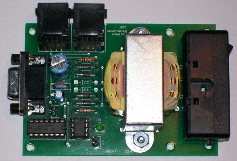
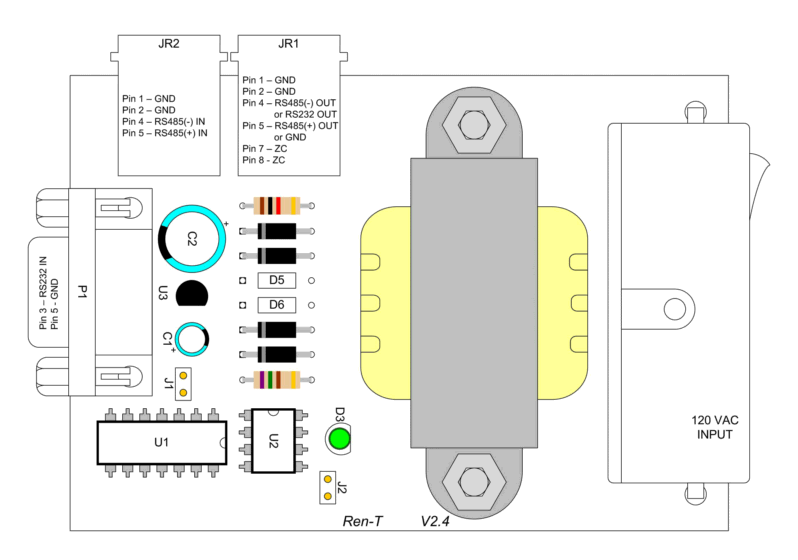
The Board
Board Versions
- V2.4 - Has provisions for mounting a dual secondary transformer. The dual secondary type transformer was later found to be undesirable for generating the Zero Crossing signal.
- V2.5 - Removed D5 & D6 and pads for the dual secondary transformer
Board Functions
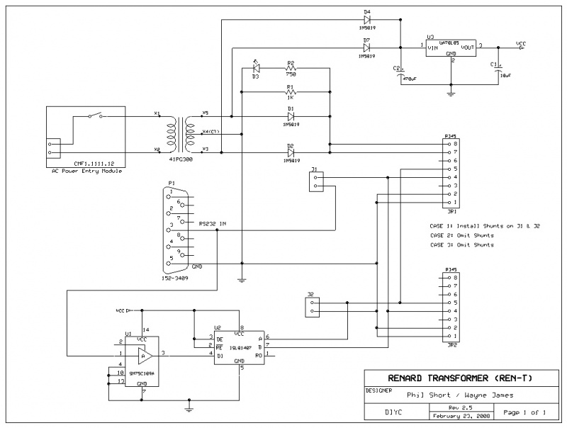
The Renard Transformer (Ren-T) board has three basic functions:
- Generate a Zero Crossing (ZC) signal
- Convert the RS232 data coming from the computer to RS485 data
- Provide a voltage that the Renard 8 can use to generate it’s own operating voltage.
Schematic Diagram
Configurations
The Ren-T can be built in three basic configurations. How the Ren-T will be used with other devices will dictate which configuration that should be used.
CASE 1:
Connecting PC to first controller without converting to RS485
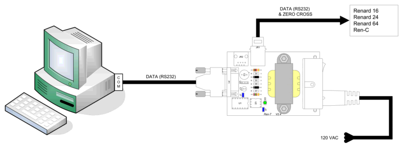
In this configuration:
- The RS232 data coming from the computer is not converted on the Ren-T. By placing the shunts on J1 and J2, the incoming RS232 data on P1 pin 3 is routed to JR1 pin 4. Also, GND on P1 pin 5 is routed to JR1 pin 5.
- The transformer output is applied to diodes D1 & D2 to generate the ZC signal that is applied to JR1 pins 7 & 8.
- Ren-T is connected to the serial port or a USB-to-Serial adapter on the controlling computer
This configuration is fine in situations where the computer, Ren-T and controller board are all in relative close proximity. RS232 data lines are usually only good for distances up to about 50 feet.
CASE 2:
Connecting one Controller to the next (RS485 pass-through)
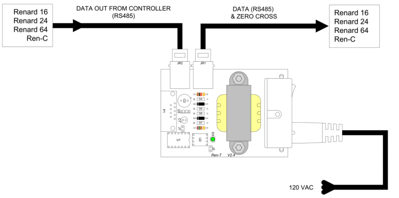
In this configuration:
- RS485 data coming out of one controller board is routed to another controller board via the Ren-T. Nothing is done to the data signal on the Ren-T, it is just routed from JR2 pins 4 & 5 straight to JR1 pins 4 & 5.
- The shunts on J1 and J2 are not installed.
- The transformer output is applied to diodes D1 & D2 to generate the ZC signal that is applied to JR1 pins 7 & 8.
- Ren-T is not connected to the controlling computer
This configuration is ideal for situations where it is desirable to connect the output of one controller to the input of a second controller that is a good distance from the first. The RS485 data signal is good for up to 4,000 feet but It is not possible to send the ZC signal over large distances without losing signal integrity. By placing a Ren-T near the input of the second controller board, you create a new ZC signal and use the RS485 data signal coming from the first controller board.
CASE 3:
Connecting PC to first controller, converting to RS485 in the process
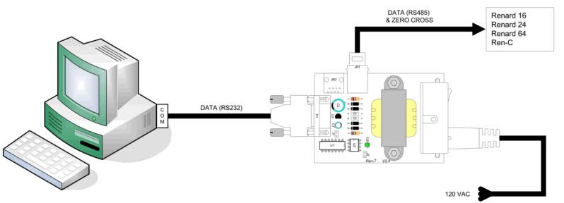
Most widely used configuration
In this configuration:
- RS232 data coming from the controlling computer is converted to RS485 data. The RS485 data is then routed to JR1 pins 4 & 5.
- The shunts on J1 and J2 are not installed.
- The transformer output is applied to diodes D1 & D2 to generate the ZC signal that is applied to JR1 pins 7 & 8.
- The transformer output is also applied to diodes D4 & D7 as input into the voltage regulator U3. U3 produces the operating voltage for U1 and U2
- Ren-T is connected to the serial port or a USB-to-Serial adapter on the controlling computer
Selecting an Alternative Transformer
There are several different possible choices of a transformer. The most basic considerations are the input voltage, the output voltage and output current ratings of the transformer. In this discussion, primary will refer to the transformers input winding(s) (that are connected to the AC power line), and secondary refers to the output winding(s) of the transformer.
The input voltage of the transformer must be the same as the AC line voltage available in your locale. You cannot use a 120VAC transformer in a location with 240 VAC power, nor can you use a 240VAC transformer if your local power is 120VAC. There are some transformers with dual primaries that can be wired up to accept either 120 or 240 VAC, but discussion of how to use these is beyond the scope of this page.
The preferred design uses a center-tapped transformer. This is a transformer which has a single output winding with three connections (one at either end of the winding, and one in the exact middle), in which the middle connection (the center-tap) is to be used. One disadvantage of this circuit is that the iron and copper in the transformer is only used with 50% effectiveness because at any point in time only half of the transformer is supplying current.
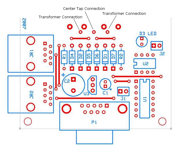
The transformer output voltage should be either 12.6VAC or 16 VAC, and the output wires from the transformer should be connected as shown here.
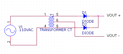
The effective schematic (taking into account the parts which are actually installed) is here:
The waveform across the output of the transformer (pins 5,8) is a sine wave with amplitude 1.41*Vtrans when fully loaded (where Vtrans would be the 12.6V or 16V rated value of the transformer). The amplitude will be somewhat higher if there is no load on the transformer or just a minimal load. The voltage between the transformer center-tap and either of the other two legs is 1/2 of this value.
The output of the rectifier circuit (VOUT+ - VOUT-) is a rectified sinewave, as shown below. The amplitude of the output waveform is (1.41*Vtrans/2 - Vf), where Vf is the forward voltage of the diodes (about 0.7V for regular diodes, 0.4V for Schottky diodes).
