SSRneon-G2-LED: Difference between revisions
Ukewarrior (talk | contribs) |
Ukewarrior (talk | contribs) |
||
| (5 intermediate revisions by 2 users not shown) | |||
| Line 52: | Line 52: | ||
The SSRneon fits in the TA-200 Telephone Demarc Enclosure from [http://www.afltele.com/products/copper_apparatus/terminal_enclosures/Keptel_TA-200_Termin_Encl.html www.afltele.com].<br> | The SSRneon fits in the TA-200 Telephone Demarc Enclosure from [http://www.afltele.com/products/copper_apparatus/terminal_enclosures/Keptel_TA-200_Termin_Encl.html www.afltele.com].<br> | ||
It is available from Chris Foley's DIY Christmas site:[http://www. | It is available from Chris Foley's DIY Christmas site:[http://www.radiant-holidays.com/ Radiant Holidays] | ||
</p><p> | </p><p> | ||
| Line 124: | Line 124: | ||
1 571-5556416-1 Modular Jacks 8 PCB TOP ENTRY marked J1 | 1 571-5556416-1 Modular Jacks 8 PCB TOP ENTRY marked J1 | ||
4 511-BTA04-700T Triacs 4 Amp 700 Volt marked U1, U2, U3, and U4 | 4 511-BTA04-700T Triacs 4 Amp 700 Volt marked U1, U2, U3, and U4 | ||
OR | |||
511-BTA06-600S Triacs 6 Amp 600 Volt marked U1, U2, U3, and U4 | |||
2 534-3517 Fuse Clips and Holders PC FUSE CLIP 5 MM | 2 534-3517 Fuse Clips and Holders PC FUSE CLIP 5 MM | ||
1 534-3527C Fuse Cover | 1 534-3527C Fuse Cover | ||
| Line 165: | Line 167: | ||
with one of the ends cut off. You can also make your own with SPT wire | with one of the ends cut off. You can also make your own with SPT wire | ||
and 'vampire' plugs/receptacles. | and 'vampire' plugs/receptacles. | ||
</pre> | </pre> | ||
'''Neon lamp alternative source information:'''<br> | |||
Jameco, www.jameco.com, sells the NE-2E neon bulb for about half of mousers price. Jameco Part Number: 210260 | |||
== Leaving out the LED Channel Indicators == | |||
'''I don't want the LED Indicators !'''<br><br> | |||
If you don't want to install the LED indicators, that is just fine, the board was designed to accommodate that wish. | |||
However, you do still need to install the resistors; BUT they need to go in different holes and have a different resistance value. | |||
You will need to use a 680 ohm resistor instead of the 220 ohm resistor. | |||
You would install this resistor with one lead in the top most resistor hole and then have it span the space down to the bottom most LED mounting hole. | |||
== How to use LEDs of many colors for the Channel Indicators == | == How to use LEDs of many colors for the Channel Indicators == | ||
Latest revision as of 19:26, 28 July 2014
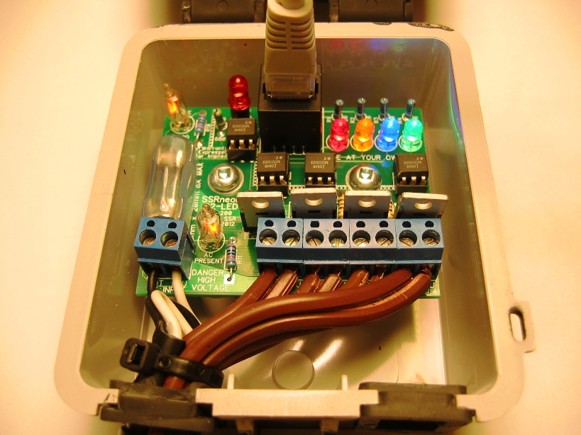
The SSR with a Safety Enhancement !
The SSRneon is a 4 port AC Solid State Relay (SSR). It is derived from the same basic design that has been in general use by the DIY community for many years. Most of the DIY SSRs are derived from Sean Bowf's original 4 port SSR. The design has evolved over the years, but the core functions and parts are the same. The SSRneon, SSRoz and SSRez are all such designs.
The SSRneon-G2-LED is a variant of the SSRneon-G2.
(ref: SSRneon-G2 wiki entry )
The current Versions of the SSRneon are SSRneon-G2 and SSRneon-G2-LED.
Safety Features
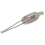

The main safety feature of any SSR is the main FUSE. (This is discussed in a separate section below.)
The SSRneon contains two NE-2E neon light bulbs.
The point of these neon lamps is they serve as a safety warning that AC voltage (which can be lethal) is present on the SSR PCB.
One bulb lights if AC voltage is correctly attached to the board. Marked AC PRESENT on the Boards Silkscreen (legend).
The second bulb lights if AC voltage has successfully passed through the on-board fuse. Marked FUSE GOOD on the Boards silkscreen (legend).
The presence of the second bulb (FUSE GOOD) serves as a troubleshooting device. If the AC PRESENT bulb is lit, but the FUSE GOOD is not, then you know that AC is connected properly, but there is something wrong with the fuse.
Neons are used instead of an incandescent bulbs due to the fact that a neon bulb is very long lived and is much 'tougher' then an incandescent since there is no filament to break.
These bulbs play no role in the basic function of the relay and can be left off the board. If this is done, the two 100K resistors can also be left off the board. The 100K resistors are needed to keep the bulbs from burning out over time.
General Features
The SSRneon-G2-LED has several key points that differentiate it from the other available SSRs.
1. Dual Neon bulbs that indicate the presence of AC Voltage !
2. The attachment of the AC wires, in AC pairs, along the bottom of the board with no wirenuts required.
3. Individual LED channel activity LEDs.
4. The 2 ounce copper AC traces are mirrored on both sides of the board. This allows for greater current carrying capacity. (8 amps)
The board has solder pads on both sides of the board and the holes are through plated. This makes for easy and more error free soldering.
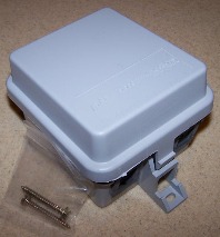
The SSRneon is designed to mount in the TA-200 enclosure. This enclosure is a proven performer.
The SSRneon fits in the TA-200 Telephone Demarc Enclosure from www.afltele.com.
It is available from Chris Foley's DIY Christmas site:Radiant Holidays
All wires attach via terminal blocks. The attachment points are along the bottom of the board facing the enclosure openings. The wire attachment is different then the other SSRs. Instead of grouping all of the neutrals and all of the 'hots' together, each individual wire 'pair' is terminated on their own terminal block. This avoids the problem of having to cut the hot and neutral wire within a pair to different lengths in order to get them to fit nicely inside the already cramped enclosure. The PCB takes care of tying all of the neutrals together for you.
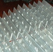
A heatsink can be fashioned and attached to the TRIACs. Use of a heatsink should boost the continuous amp capacity from 4 amps to 8 amps. A heatsink should not be necessary unless the load for any single channel (Tirac) exceeds 1 amp. These are usually made from a piece of aluminum since it cuts and drills easily and absorbs heat rapidly. See the example to the right of a couple dozen homemade headsinks. One safety note about heatsinks. You need to be sure the TRIACs you are using have what is know as an 'isolated tab.' The tab is the exposed metal pad with the hole in it. On some TRIACs the tab is 'hot' or has AC voltage present. You should not use a heatsink that connects all of the TRIACS together unless all the TRIACs have an 'isolated tab'. The TRIAC listed in the BOM has an 'isolated tab' so it is suitable for use with a heatsink.
The board has two points to mount it to the TA-200 enclosure. Great pains were taken to make sure that the screws that come with the enclosure can be used once they have been cut down to a proper length. You can use the screws that come with the enclosure provided you cut them off. The correct length of the cut off shaft BELOW the head is 5/8".
The screws that come with the enclosure are nice in that they have both a hex head and a screw driver slot for installation/removal. (Plus they are free with the enclosure!)
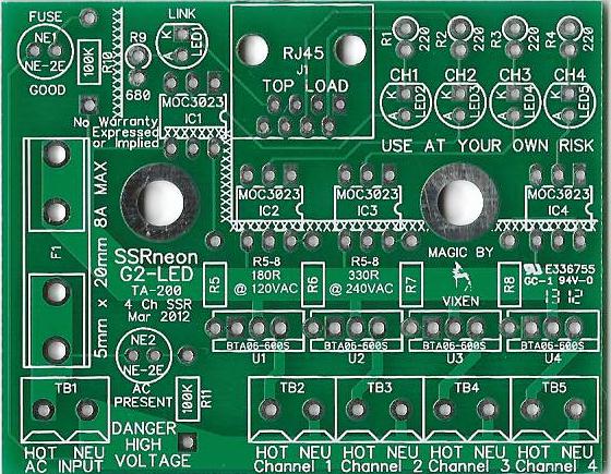
The Schematic can be viewed by clicking on this link:
SSRneon-G2-LED Schematic
.
Order your own boards
You can order your own boards with the information given below, or you can contact: gmbartlett on the DIYC forum to see if he has any in stock.
The PCB industry has a standard for the definition of a PCB. It's called a 'gerber' file. This is a set of files that have the actual instructions that tell the machines how to operate.
The Gerbers for the SSRneon-G2-LED are found at this link: Zip File containing the SSRneon-G2-LED Gerber files
This is all your should need to order PCBs from any PCB manufacturer.
Home Etch
The SSRneon-G2-LED is a two sided board with tolerances that do not lend themselves to home etching.
If you want to home etch an SSR, please go to the wiki entry for the SSRneon-G2 which is a home etch friendly design and has design files specifically built for home etching.
(ref: SSRneon-G2 wiki entry )
Fuse Rating
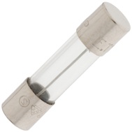
The main Fuse exists to protect both people and the components on the board.
Various fuse values have been listed for all the various 4 port SSRs. e.g. SSRneon, Sean Bowf, SSRoz, SSRez.
The fuse value is determined by several factors. Key among these is the amount of current, in total, that is flowing through the SSR. Another factor is the copper weight and size of the main AC traces. (Copper weight is how 'thick' the copper is on the board.)
The SSRneon-G2 has the largest amount of AC trace copper weight of any of the DIY SSRs to date. (4/22/2012) With that said, a Fuse of 4 amps is a good place to start. If you want to drive more then 1 amp through any individual TRIAC (channel), then you can ramp up to as high as an 8 amp fuse. However, once you move above 1 amp through any single TRIAC (channel), you should put a heat sink on the TRIAC(s). This does not mean you can run 8 amps through a single TRIAC (channel). A single TRIAC can handle 2.0 amps max. You will notice that the copper traces that connect to any one TRIAC are no where near the size of the main AC copper trace. So, just because the TRIAC you use may be rated for 3 or 4 or more amps doesn't mean the SSRneon-G2-LED can safely drive it at that amperage.
It is this authors opinon that you should run as low a fuse value as possible for your needs. For example, this author runs a 100% LED based show and runs several SSRneons with 2 amp fuses.
Disclaimers
USE the SSRneon-G2-LED at Your Own Risk !
The SSRneon-G2-LED has NO warranty expressed or implied
BOM - Bill of Materials
The following BOM assumes that the four channel indicator LEDs are RED LEDs. If you want to use other colors for the indicators, see the section after the BOM for a discussion on how to use other colors.
BOM for 120VAC Operation:
QTY    Mouser #:           Description
2      606-A9A            Neon Lamp 65VAC .7mA NE-2E marked NE1, NE2  (See the note below for an alternative source)
1      571-5556416-1      Modular Jacks 8 PCB TOP ENTRY marked J1
4      511-BTA04-700T     Triacs 4 Amp 700 Volt marked U1, U2, U3, and U4
            OR
       511-BTA06-600S     Triacs 6 Amp 600 Volt marked U1, U2, U3, and U4
2      534-3517           Fuse Clips and Holders PC FUSE CLIP 5 MM
1      534-3527C          Fuse Cover
5      604-WP7104IT       LED Standard HI EFF RED TRANS marked LED1, LED2, LED3, LED4, LED5
1      660-CF1/4C681J     1/4Watt Axial Carbon Film Resistors 680ohms 5% marked R9
4      660-CF1/4C221J     1/4Watt Axial Carbon Film Resistors 220ohms 5% marked R1, R2, R3, R4
4      660-CF1/4C181J     1/4Watt Axial Carbon Film Resistors 180ohms 5% marked R5, R6, R7 & R8
2      660-CF1/4C104J     1/4Watt Axial Carbon Film Resistors 100Kohms 5% marked R10, R11
4      859-MOC3023        Optocomponents Optocoupler marked IC1, IC2, IC3 and IC4
4      571-1-390261-1     IC Sockets 6P ECONOMY TIN marked IC1, IC2, IC3, IC4
5      571-2828372        Terminal Blocks 5.08MM PCB MOUNT 2P marked TB1, TB2, TB3, TB4, TB5

Note regarding resistors.  You usually want to purchase resistors from Mouser in quantities
of 100 of a specific value.  You usually can get 100 resistors for the same price of
20 individual resistors.  (You will eventually use them !)


As noted above in the FUSE Section, you have a choice to make.
You only need one fuse per SSRneon.
You should always order extra fuses.

1      504-GMC-2          5mm x 20mm Medium Time Delay Fuses 125VAC 2A Med Time Delay
1      504-GMC-3          5mm x 20mm Medium Time Delay Fuses 125VAC 3A Med Time Delay
1      504-GMC-4          5mm x 20mm Medium Time Delay Fuses 125VAC 4A Med Time Delay
1      504-GMC-5          5mm x 20mm Medium Time Delay Fuses 125VAC 5A Med Time Delay
1      504-GMC-6          5mm x 20mm Medium Time Delay Fuses 125VAC 6A Med Time Delay
1      504-GMC-7          5mm x 20mm Medium Time Delay Fuses 125VAC 7A Med Time Delay
1      504-GMC-8          5mm x 20mm Medium Time Delay Fuses 125VAC 8A Med Time Delay

The following items are NOT available from Mouser.
You can get everything but the TA-200 from your local hardware store or home center.
See above for TA-200 sources.

2                         Screw,#8x1/2" Pan Head Sheet Metal
                          (You can use the screws that come with the TA-200 if you cut them down)
1      TA-200             Enclosure
1                         Male Plug Power Cord, Rated for 10A Minimum
4                         Female Plug Power Cord, Rated for 4A Minimum

The power cords are often fashioned from standard household extension cords
with one of the ends cut off.  You can also make your own with SPT wire
and 'vampire' plugs/receptacles.
Neon lamp alternative source information:
Jameco, www.jameco.com, sells the NE-2E neon bulb for about half of mousers price. Jameco Part Number: 210260
Leaving out the LED Channel Indicators
I don't want the LED Indicators !
If you don't want to install the LED indicators, that is just fine, the board was designed to accommodate that wish.
However, you do still need to install the resistors; BUT they need to go in different holes and have a different resistance value.
You will need to use a 680 ohm resistor instead of the 220 ohm resistor. You would install this resistor with one lead in the top most resistor hole and then have it span the space down to the bottom most LED mounting hole.
How to use LEDs of many colors for the Channel Indicators
Using other colors than red for the channel indicator
The board was designed and silkscreened to use a 220 ohm resistor and red LED for the the channel indicator.
However, other colors can be used.
Red LEDs have a typical forward voltage (Vf) of 2.0 volts. However, other colors, like green, have a Vf of 3.x volts. Therefore, if you use a LED with a Vf in this range, you should replace the 220 ohm resistor connected to that LED with a 180 ohm resistor.
The basic equation is:
R = [V(supply) - Vf(opto) - Vf(LED) - Vol]/0.005
V(supply): Supply voltage, in our case 5V
Vf(opto): Forward voltage of the opto emitter, 1.5V max, 1.15 typ
Vf(LED): Forward voltage of the LED, for the LEDs I use it is 2.0V
Vol: Low voltage output level, For the purposes of this calculation, a value of 0.33V max, 0.18V typical was used.
So R = [5 - 1.5 - 2.0 - 0.33]/0.005 = 234 ohms or the next lower standard value is 220 ohms
This doesn't take into account the tolerances of the resistor but given the worst case values for the opto emitter and Vol this shouldn't matter.
So if we look at the typical case the current draw would be:
I = [5 - 1.15 - 2.05 - 0.18]/220 = 7.36 mA.
This is about 50% more current than the desired 5 mA but the SSR is guaranteed to fire even under the worst case.
If you are concerned about the current draw then you can increase the value of R based on the typical values (i.e. to either 270 or 300). However, there is a concern that with the temperature extremes these devices are used in, this would push them closer to the max values and cause erratic behavior.
Construction Information
There are several 'how to build a PCB' self help guides both within this wiki and the web.
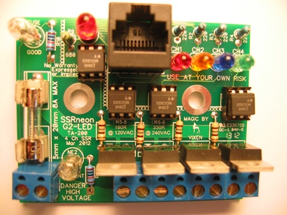
Here is a picture of a completed SSRneon-G2: (The fuse cover has been removed)

Wiring The SSRneon
The pin-out for the RJ-45 network cable is the same for all of the Sean Bowf derivative SSRs:
View looking down on the component side of the PCB:
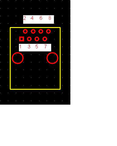 |
Controller Output Pinout
|
The following image shows how to connect wires to the SSRneon-G2-LED.
The AC line connects to the far left hand terminal block labeled: AC INPUT
The other four terminal blocks are for the wires that will connect to your lights. The connector labeled: HOT is for the 'hot' wire. The connector labeled: NEU is for the 'neutral' wire.
Your network interface cable clicks into the RJ45 connector on the top right of the board. If all is well, you should see both neon bulbs glowing signaling AC voltage is present and flowing through the fuse. The LED should also be lit to indicate that 5 volts DC is being supplied by the lighting controller.
