4 Channel DCSSR Assembly Instructions: Difference between revisions
Jump to navigation
Jump to search
(New page: == Background == The DC SSR project was commenced at the request of James Melvin, who wanted to control some DC Devices for Halloween. We worked on this projec and had some prototype boar...) |
No edit summary |
||
| Line 1: | Line 1: | ||
== Background == | == Background == | ||
The DC SSR project was commenced at the request of | The DC SSR project was commenced at the request of Scott Nethring, who wanted to control some DC Devices for Halloween. We worked on this projec and had some prototype boards working for the shows, and I have subesquently tested the DC SSRs with | ||
| Line 15: | Line 15: | ||
1 7805 or 78L05 | 1 7805 or 78L05 | ||
5 538-39890-0302 Screw terminals | 5 538-39890-0302 Screw terminals | ||
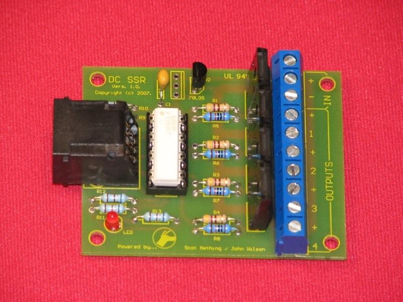
== Completed DC SSR == | |||
[[Image:DC SSR.jpg]] | |||
Revision as of 23:04, 10 November 2007
Background
The DC SSR project was commenced at the request of Scott Nethring, who wanted to control some DC Devices for Halloween. We worked on this projec and had some prototype boards working for the shows, and I have subesquently tested the DC SSRs with
Parts List
 4 MOSFETs  512-RFP14N05L
 1 OPTO 782-K847PH
 5 680 ohm resistors
 4 470 ohm resistors
 4 10k resistors
 1 LED
 1 RJ socket
 1 7805 or 78L05
 5 538-39890-0302 Screw terminals
