Firegod: Difference between revisions
No edit summary |
No edit summary |
||
| Line 4: | Line 4: | ||
One (1) PC interface | One (1) PC interface | ||
Four (4) field modules | Four (4) field modules | ||
A system MUST have one PC interface and one field module. Up to four field modules may be used. | A system MUST have one PC interface and one field module. Up to four field modules may be used. | ||
| Line 31: | Line 34: | ||
== Serial Data Protocol: == | == Serial Data Protocol: == | ||
The serial data consists of three elements: | The serial data consists of three elements: | ||
A sync character (55h or 85dec) | A sync character (55h or 85dec) | ||
A module address (1, 2, 3, or 4) | A module address (1, 2, 3, or 4) | ||
32 bytes of dimming level data (64h to C8 or 100dec to 200dec) | 32 bytes of dimming level data (64h to C8 or 100dec to 200dec) | ||
The scync character is not used but can be used for automatically detecting the baud rate. | The scync character is not used but can be used for automatically detecting the baud rate. | ||
Revision as of 20:37, 26 April 2008
This is a modular system that supports 32 to 128 channels per serial port, in increments of 32 channels.
The system consists of five separate PCB boards:
One (1) PC interface
Four (4) field modules
A system MUST have one PC interface and one field module. Up to four field modules may be used.
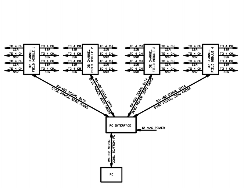
The overall architecture of the system looks like this:
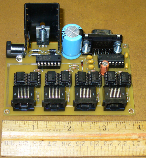
The PC Interface is responsible for providing power to the field modules, input data to the field modules, output data from the field modules, and a zero cross signal to the field modules. These signals are sent from the PC interface to/from the field module via CAT 5 cables. The PC interface is powered by a 12VAC transformer.
The field module receives data from the PC interface via the RS485 serial link. Data can be sent back to the PC interface from the PIC chip. Currently the only data that is sent is the voltage level from the four selectable jumpers on the field module during the bootup of the PIC chip. These jumpers define what module number is assigned to the field module.
The PC interface looks like this:
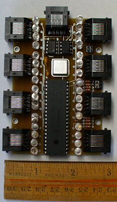
The field modules look like this:
The field modules have optional LEDs on the boards. If the LEDs are installed, the SSR resitor should be 510 ohms. The installation direction of the optional LEDs is depenent on the type of SSRs or end device being used. Care should be taken when installing the LEDs.
Serial Data Protocol:
The serial data consists of three elements:
A sync character (55h or 85dec)
A module address (1, 2, 3, or 4)
32 bytes of dimming level data (64h to C8 or 100dec to 200dec)
The scync character is not used but can be used for automatically detecting the baud rate. The field module waits for an address (1, 2, 3, 4) and once it sees its address, it stores the next 32 bytes of data into the array used for dimming.
The default baud rate is 115.2 kbps.


