DMX to Grinch/595 convertor: Difference between revisions
No edit summary |
No edit summary |
||
| Line 1: | Line 1: | ||
By Robert P Martin aka RPM | |||
Like many others here, I too started out with a Grinch controller. It worked, but I soon realized that I wanted to have dimming, so this meant I had to build another controller, or build my own dimming adapter. | |||
After looking at the options at the time, I decided to build my own dimming interface for my Grinch controller. I also wanted to use the DMX protocol, since I wanted to run my controller out in the yard some distance from my show computer in my garage, and by using DMX I could easily do this. | |||
After a few months of trying different design prototypes, this is the design I came up with: | |||
[[Image:Grinch_DMX_Dimmer_V2.jpg]] | |||
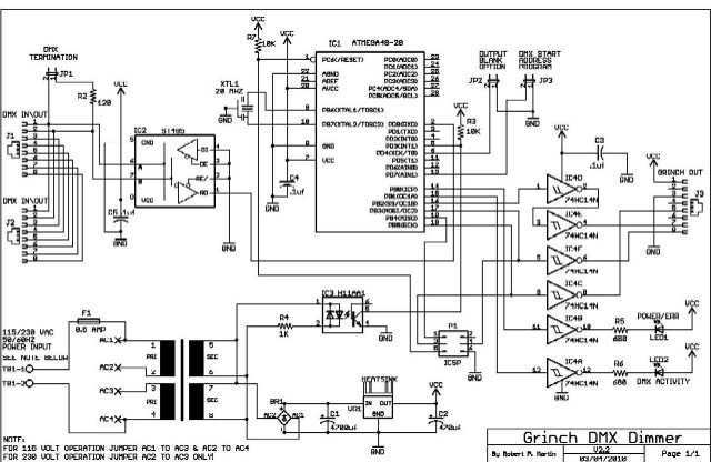
[[Image:GrinchDMXdim_SCHEMATIC.JPG]] | |||
I used this design in my display to run my Grinch controllers for my entire show the first year I ran a computerized show, and I continue to use it to run my 32 channel Megatree and it works very well, and best of all it dims! | |||
This is brief a explanation of the operation: | |||
JP1 is a termination jumper for the DMX signal. If this is the LAST device on the DMX line, put the jumper JP1 on it to terminate the 120 ohm resistor across the DMX buss. The DMX signal does not like to be unterminated, and if left unterminated it can do some strange things. If you have other DMX devices to hook up after this, plug them into this board and do not jumper JP1 the terminator on this board. | |||
This is a | J1 on your Grinch controller should be jumpered so that the positive +5 side for operation will be provided through the RJ45 connector from the Grinch DMX dimmer adapter board. | ||
This board uses what I call the "jumperless" method of setting the DMX start channel, so will also need to program the starting channel into the board before it will work. | |||
It uses the sum of the first two DMX channels (channel 1 & 2) as the start channel address. This is done by powering the board off, then start vixen with the DMX plugin set for the all the channels. Set the intensity levels to use the 256 level mode not the 100% mode. Create a sequence of 3 seconds or more and set the first channel to the intensity value of the channel you want the board to use as the first channel for the whole 3 seconds so this is the only value output for this channel. If you want the board to start on a channel higher than 255 than simply add the additional to the second channel. | |||
For example, to start at channel 300, the first channel is set to 255 and the second is set to 45. Now make sure vixen is set to repeat the sequence and start it. Now with the power still off on the board put the JP3 jumper on and power up the board for 3 seconds. The board will light LED1 and LED 2 solid to indicate that the programming has been saved. | |||
Now turn power to the board off and remove JP3 (operation mode). Your board DMX start channel is now programmed. Remember in my example (channel 300) I would use vixens channel 300 - 364 to control my board now. If it doesn't act like you think it should, reprogram it to channel 1 and try it. An easy way to "default" the board back to a start channel of 1 is to place JP3 on and remove the DMX input cable, power the board on until LEDs 1 & 2 light solid, power off, remove JP3 and when you power back up it will be set back to start channel 1. | |||
You may reprogram it as much as you like the life of the EEPROM is over 1 million cycles so you should have a hard time breaking it. It will remember the information for about 40 years with the power off so you dont have to reprogram it unless you want to change the channel assigned. | |||
A straight through cable should be used between the converter and the Grinch/595 board. This converter will run 64 channels, so you will need one converter per Grinch controller. | |||
The distance from the converter to the Grinch/595 should be as short as possible. I use a 1 foot cable with mine and mount it in the same enclosure as my Grinch controller. | |||
The distance from the | |||
I | |||
Revision as of 06:50, 17 April 2010
By Robert P Martin aka RPM
Like many others here, I too started out with a Grinch controller. It worked, but I soon realized that I wanted to have dimming, so this meant I had to build another controller, or build my own dimming adapter.
After looking at the options at the time, I decided to build my own dimming interface for my Grinch controller. I also wanted to use the DMX protocol, since I wanted to run my controller out in the yard some distance from my show computer in my garage, and by using DMX I could easily do this.
After a few months of trying different design prototypes, this is the design I came up with:
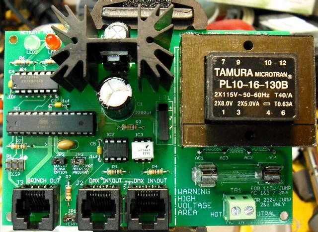


I used this design in my display to run my Grinch controllers for my entire show the first year I ran a computerized show, and I continue to use it to run my 32 channel Megatree and it works very well, and best of all it dims!
This is brief a explanation of the operation:
JP1 is a termination jumper for the DMX signal. If this is the LAST device on the DMX line, put the jumper JP1 on it to terminate the 120 ohm resistor across the DMX buss. The DMX signal does not like to be unterminated, and if left unterminated it can do some strange things. If you have other DMX devices to hook up after this, plug them into this board and do not jumper JP1 the terminator on this board.
J1 on your Grinch controller should be jumpered so that the positive +5 side for operation will be provided through the RJ45 connector from the Grinch DMX dimmer adapter board. This board uses what I call the "jumperless" method of setting the DMX start channel, so will also need to program the starting channel into the board before it will work. It uses the sum of the first two DMX channels (channel 1 & 2) as the start channel address. This is done by powering the board off, then start vixen with the DMX plugin set for the all the channels. Set the intensity levels to use the 256 level mode not the 100% mode. Create a sequence of 3 seconds or more and set the first channel to the intensity value of the channel you want the board to use as the first channel for the whole 3 seconds so this is the only value output for this channel. If you want the board to start on a channel higher than 255 than simply add the additional to the second channel.
For example, to start at channel 300, the first channel is set to 255 and the second is set to 45. Now make sure vixen is set to repeat the sequence and start it. Now with the power still off on the board put the JP3 jumper on and power up the board for 3 seconds. The board will light LED1 and LED 2 solid to indicate that the programming has been saved. Now turn power to the board off and remove JP3 (operation mode). Your board DMX start channel is now programmed. Remember in my example (channel 300) I would use vixens channel 300 - 364 to control my board now. If it doesn't act like you think it should, reprogram it to channel 1 and try it. An easy way to "default" the board back to a start channel of 1 is to place JP3 on and remove the DMX input cable, power the board on until LEDs 1 & 2 light solid, power off, remove JP3 and when you power back up it will be set back to start channel 1.
You may reprogram it as much as you like the life of the EEPROM is over 1 million cycles so you should have a hard time breaking it. It will remember the information for about 40 years with the power off so you dont have to reprogram it unless you want to change the channel assigned.
A straight through cable should be used between the converter and the Grinch/595 board. This converter will run 64 channels, so you will need one converter per Grinch controller.
The distance from the converter to the Grinch/595 should be as short as possible. I use a 1 foot cable with mine and mount it in the same enclosure as my Grinch controller.