Renard Data Cables: Difference between revisions
No edit summary |
No edit summary |
||
| Line 1: | Line 1: | ||
'''The data cables shown on this page apply to the current Renard board designs at DIYC, except the [[Renard 16 Controller | Renard 16 (xmus)]] which has unique requirements. <br> Some earlier designs/prototypes may have different cable requirements, when in doubt check the dedicated wiki page for that particular board.''' | '''The data cables shown on this page apply to the current Renard board designs at DIYC, except the [[Renard 16 Controller | Renard 16 (xmus)]] which has unique requirements. <br> Some earlier designs/prototypes may have different cable requirements, when in doubt check the dedicated wiki page for that particular board.''' | ||
==Data Cables== | |||
===Directly to computer COMM port (DE9 to DE9 connection)=== | |||
[[image: wiki - Serial to Renard DE9 Connection.jpg | 600px ]] | [[image: wiki - Serial to Renard DE9 Connection.jpg | 600px ]] | ||
Mainly for Renard 64XC and Renard SS boards | Mainly for Renard 64XC and Renard SS boards | ||
| Line 8: | Line 9: | ||
PC DE9 Pin 5 to Renard DE9 Pin 5 | PC DE9 Pin 5 to Renard DE9 Pin 5 | ||
===Directly to computer COMM port (DE9 to RJ45 connection)=== | |||
[[image: wiki - Serial to Renard RJ45 Connection.jpg | 600px ]] | [[image: wiki - Serial to Renard RJ45 Connection.jpg | 600px ]] | ||
| Line 14: | Line 17: | ||
==Using a RS232->RS485 or USB->RS485 converter== | ===Using a RS232->RS485 or USB->RS485 converter=== | ||
::Due to the many different types of RS232->RS485 and USB->RS485 converters available, the drawing only refers to the signals coming from the converter. Check the documentation for your converter to figure out how/where to hook up the correct wires. | ::Due to the many different types of RS232->RS485 and USB->RS485 converters available, the drawing only refers to the signals coming from the converter. Check the documentation for your converter to figure out how/where to hook up the correct wires. | ||
| Line 25: | Line 28: | ||
==In a DMX environment== | ===In a DMX environment=== | ||
[[image:wiki - DMX (XLR) to Renard Connection.jpg | 600px]] <br> | [[image:wiki - DMX (XLR) to Renard Connection.jpg | 600px]] <br> | ||
| Line 41: | Line 44: | ||
==Connecting multiple Renard boards== | ===Connecting multiple Renard boards=== | ||
[[image:Wiki - Renard to Renard Data Cable.jpg | 600px]] <br> | [[image:Wiki - Renard to Renard Data Cable.jpg | 600px]] <br> | ||
Generally only a regular straight-thru CAT5 cable is required to connect a Renard board to other Renard boards. | Generally only a regular straight-thru CAT5 cable is required to connect a Renard board to other Renard boards. | ||
For the few exceptions (ie Ren24 V2.5), check the wiki page for those boards to see what their unique requirements are. | For the few exceptions (ie Ren24 V2.5), check the wiki page for those boards to see what their unique requirements are. | ||
==Adapters/Converters== | |||
<blockquote>'''Note to reader:''' The following adapters are examples of some of the common adapters that are available on eBay and other on-line sources. All of these adapters were tested during the writing of this wiki page. But since most of the sources for these adapters are in China, the quality of any given product may vary greatly. So while this batch of adapters worked there are no guarantees that future items from China will perform also, so please do not blame the author of this page if you happen to get an adapter that doesn't perform well.</blockquote> | |||
===DE9 to RJ-45 Adapter === | |||
:This easy to use adapter is great for converting from the serial DE9 connector on most computers/adapters to a CAT5 RJ-45 connector. This allows you to use normal CAT5 cables to connect your computer to the controllers. | |||
:Below is what appears to be the common color coding for the RJ-45 pin assignments. While all samples that were found during the writing of this article followed the same color coding, you should always double check any adapters that you might decide to use. | |||
:::{|border="0" cellpadding="10" style="text-align: left;" | |||
|- | |||
|[[image:DE9 to RJ45 Adapter.JPG | 300px]] | |||
| ''' RJ45 Wire <br> Pin# Color''' | |||
1 Blue | |||
<br> 2 Orange | |||
<br> 3 Black | |||
<br> 4 Red | |||
<br> 5 Green | |||
<br> 6 Yellow | |||
<br> 7 Brown | |||
<br> 8 White | |||
|} | |||
:'''Modification for using this adapter for RS-232''' | |||
::*Remove the wires for unused pins (3-black, 6-yellow, 7-brown, 8-white). Cut the wires off as far down in the adapter as possible because you will need one of these wires later. | |||
::*Cut the pins off of wires for pin 1-blue, 2-orange, 5-green. | |||
::*Solder the above wires together, along with one of the wires cut off in the first step. | |||
::*Use some heat shrink tubing to cover the soldered area. | |||
::*Insert the pin on the wire connecting the soldered together wires into DE9 connector pin 5. | |||
::*Insert the pin on the red wire (RJ45, pin 4) into DE9 connector pin 3. | |||
:::[[image:RS232 modded DE9-R45 adapter.jpg | 300px]] | |||
:'''Modification for using this adapter for common RS-485 adapters''' | |||
::*Remove the wires for unused pins (3-black, 6-yellow, 7-brown, 8-white). Cut the wires off as far down in the adapter as possible because you will need one of these wires later. | |||
::*Cut the pins off of wires for pin 1-blue, 2-orange. | |||
::*Solder the above wires together, along with one of the wires cut off in the first step. | |||
::*Use some heat shrink tubing to cover the soldered area. | |||
::*Insert the pin on the wire connecting the soldered together wires into DE9 connector pin 5. | |||
::*Insert the pin on the red wire (RJ45, pin 4) into DE9 connector pin 1. | |||
::*Insert the pin on the green wire (RJ45, pin 5) into DE9 connector pin 2. | |||
:::[[image:RS485 modded DE9-R45 adapter.JPG | 300px]] | |||
===USB to RS-232 Converters=== | |||
:'''Unitek Model: Y-105''' | |||
:::[[image:Unitek USB to RS232 Converter.JPG | 300px]] | |||
:'''Generic model''' | |||
:::[[image:USB to RS232 Converter.JPG | 300px]] | |||
::*The output connector of each converter above is the same, so the converters are hooked-up in the same fashion. | |||
::USB to RS-232 Converter attached to a DE9 to RJ-45 adapter | |||
:::[[image:USB-RS232-RJ45.JPG| 300px |]] | |||
::USB to RS-232 Converter attached to a RS-232 to RS-485 converter using the terminal board method. | |||
:::[[image:USB to RS232 Converter with RS485.JPG | 300px]] | |||
::USB to RS-232 Converter attached to a RS-232 to RS-485 converter a DE9 to RJ-45 adapter. | |||
:::[[image:USB-RS232-RS485-RJ45.JPG | 300px]] | |||
===USB to RS-485 Converters=== | |||
:'''Hexin Model: HXSP-2108F''' | |||
:::[[image:HXSP-2108F USB to RS485 Converter.JPG | 300px]] | |||
:'''Generic model''' | |||
:::[[image:USB to RS485 Converter.JPG | 300px]] | |||
::*The output connector of each converter above is the same, so the converters are hooked-up in the same fashion. | |||
::USB to RS-485 Converter attached to a DE9 to RJ-45 adapter | |||
:::[[image:HXSP-2108F USB to RS485 Converter to RJ45.JPG | 300px]] | |||
::USB to RS-485 Converter using the terminal board method. | |||
:::[[image:HXSP-2108F USB to RS485 Converter (wired).JPG | 300px]] | |||
Adapter board signal T-/A connects to RJ45-pin 4 (blue CAT5 wire) | |||
Adapter board signal T+/B connects to RJ45-pin 5 (blue/white CAT5 wire) | |||
Adapter board GND signal connects to RJ45-pins 1 & 2 (orange and orange/white CAT5 wires) | |||
===RS-232 to RS-485 Converters=== | |||
:'''Hexin Model: 485 (Style 1)''' | |||
:::[[image:Hexin RS232 to RS485 converter.jpg | 300px]] | |||
:::[[image:Hexin RS232 to RS485 (wired).JPG | 300px]] | |||
Adapter board signal T/R- connects to RJ45-pin 4 (blue CAT5 wire) | |||
Adapter board signal T/R+ connects to RJ45-pin 5 (blue/white CAT5 wire) | |||
Adapter board GND signal connects to RJ45-pins 1 & 2 (orange and orange/white CAT5 wires) | |||
:'''Hexin Model: 485 (Style 2)''' | |||
:::[[image:Hexin RS232 to RS485 converter V2.jpg | 300px]] | |||
:::[[image:Hexin RS232 to RS485 V2 (wired).JPG | 300px]] | |||
Adapter board signal 485+ connects to RJ45-pin 5 (blue/white CAT5 wire) | |||
Adapter board signal 485- connects to RJ45-pin 4 (blue CAT5 wire) | |||
Adapter board GND signal connects to RJ45-pins 1 & 2 (orange and orange/white CAT5 wires) | |||
:'''Sintech Model: 485C''' | |||
:::[[image:Sintech RS232 to RS485 converter.JPG | 300px]] | |||
:'''Sintech Model: STM485S''' | |||
:::[[image:RS232 to RS485 converter V1.JPG | 300px]] | |||
:::[[image:RS232 to RS485 converter (wired) V1.JPG | 300px]] | |||
Adapter board signal D+/A connects to RJ45-pin 5 (blue/white CAT5 wire) | |||
Adapter board signal D-/B connects to RJ45-pin 4 (blue CAT5 wire) | |||
Adapter board GND signal connects to RJ45-pins 1 & 2 (orange and orange/white CAT5 wires) | |||
::*All the above RS-232 to RS-485 adapters have the same pin configuration of the output connector, so they all can use the same modified DE9 to RJ-45 adapter. | |||
:::[[image:RS232 to RS485 converter to RJ45.JPG | 300px]] | |||
Revision as of 02:54, 28 February 2011
The data cables shown on this page apply to the current Renard board designs at DIYC, except the Renard 16 (xmus) which has unique requirements.
Some earlier designs/prototypes may have different cable requirements, when in doubt check the dedicated wiki page for that particular board.
Data Cables
Directly to computer COMM port (DE9 to DE9 connection)

Mainly for Renard 64XC and Renard SS boards
  PC DE9 Pin 3 to Renard DE9 Pin 3
  PC DE9 Pin 5 to Renard DE9 Pin 5
Directly to computer COMM port (DE9 to RJ45 connection)

PC DE9 Pin 3 to RJ45-pin 4
PC DE9 Pin 5 to RJ45-pin 5 and pin 1 and/or pin 2
Using a RS232->RS485 or USB->RS485 converter
- Due to the many different types of RS232->RS485 and USB->RS485 converters available, the drawing only refers to the signals coming from the converter. Check the documentation for your converter to figure out how/where to hook up the correct wires.

Converter signal RS485(-)/T-/D-/B/485- connects to RJ45-pin 4 (blue CAT5 wire)
Converter signal RS485(+)/T+/D+/A/485+ connects to RJ45-pin 5 (blue/white CAT5 wire)
Converter GND signal connects to RJ45-pins 1 & 2 (orange and orange/white CAT5 wires)

        An example is shown here with the HXSP-2108F Adapter Hook-up
In a DMX environment
_to_Renard_Connection.jpg)
_to_Renard_Connection.jpg)
DMX using XLR Connectors
   XLR connector pin 1 (GND) to RJ45-pin 1 and/or pin 2
   XLR connector pin 2 (Data-) to RJ45-pin 4
   XLR connector pin 3 (Data+) to RJ45-pin 5

DMX using RJ45 (CAT5) Connectors
   RJ45 connector pin 1 (Data+) to RJ45-pin 5
   RJ45 connector pin 2 (Data-) to RJ45-pin 4
   RJ45 connector pins 7 & 8 (GND) to RJ45-pins 1 & 2
Connecting multiple Renard boards

Generally only a regular straight-thru CAT5 cable is required to connect a Renard board to other Renard boards.
For the few exceptions (ie Ren24 V2.5), check the wiki page for those boards to see what their unique requirements are.
Adapters/Converters
Note to reader: The following adapters are examples of some of the common adapters that are available on eBay and other on-line sources. All of these adapters were tested during the writing of this wiki page. But since most of the sources for these adapters are in China, the quality of any given product may vary greatly. So while this batch of adapters worked there are no guarantees that future items from China will perform also, so please do not blame the author of this page if you happen to get an adapter that doesn't perform well.
DE9 to RJ-45 Adapter
- This easy to use adapter is great for converting from the serial DE9 connector on most computers/adapters to a CAT5 RJ-45 connector. This allows you to use normal CAT5 cables to connect your computer to the controllers.
- Below is what appears to be the common color coding for the RJ-45 pin assignments. While all samples that were found during the writing of this article followed the same color coding, you should always double check any adapters that you might decide to use.
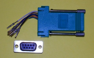
RJ45 Wire
Pin# Color1 Blue
2 Orange
3 Black
4 Red
5 Green
6 Yellow
7 Brown
8 White

- Modification for using this adapter for RS-232
- Remove the wires for unused pins (3-black, 6-yellow, 7-brown, 8-white). Cut the wires off as far down in the adapter as possible because you will need one of these wires later.
- Cut the pins off of wires for pin 1-blue, 2-orange, 5-green.
- Solder the above wires together, along with one of the wires cut off in the first step.
- Use some heat shrink tubing to cover the soldered area.
- Insert the pin on the wire connecting the soldered together wires into DE9 connector pin 5.
- Insert the pin on the red wire (RJ45, pin 4) into DE9 connector pin 3.

- Modification for using this adapter for common RS-485 adapters
- Remove the wires for unused pins (3-black, 6-yellow, 7-brown, 8-white). Cut the wires off as far down in the adapter as possible because you will need one of these wires later.
- Cut the pins off of wires for pin 1-blue, 2-orange.
- Solder the above wires together, along with one of the wires cut off in the first step.
- Use some heat shrink tubing to cover the soldered area.
- Insert the pin on the wire connecting the soldered together wires into DE9 connector pin 5.
- Insert the pin on the red wire (RJ45, pin 4) into DE9 connector pin 1.
- Insert the pin on the green wire (RJ45, pin 5) into DE9 connector pin 2.

USB to RS-232 Converters
- Unitek Model: Y-105

- Generic model

- The output connector of each converter above is the same, so the converters are hooked-up in the same fashion.
- USB to RS-232 Converter attached to a DE9 to RJ-45 adapter
- USB to RS-232 Converter attached to a DE9 to RJ-45 adapter

- USB to RS-232 Converter attached to a RS-232 to RS-485 converter using the terminal board method.
- USB to RS-232 Converter attached to a RS-232 to RS-485 converter using the terminal board method.

- USB to RS-232 Converter attached to a RS-232 to RS-485 converter a DE9 to RJ-45 adapter.
- USB to RS-232 Converter attached to a RS-232 to RS-485 converter a DE9 to RJ-45 adapter.

USB to RS-485 Converters
- Hexin Model: HXSP-2108F

- Generic model

- The output connector of each converter above is the same, so the converters are hooked-up in the same fashion.
- USB to RS-485 Converter attached to a DE9 to RJ-45 adapter
- USB to RS-485 Converter attached to a DE9 to RJ-45 adapter

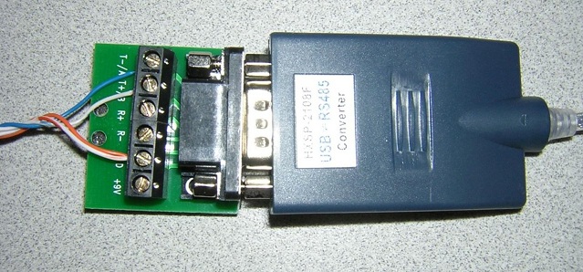
- USB to RS-485 Converter using the terminal board method.
- USB to RS-485 Converter using the terminal board method.
.JPG)
Adapter board signal T-/A connects to RJ45-pin 4 (blue CAT5 wire)
Adapter board signal T+/B connects to RJ45-pin 5 (blue/white CAT5 wire)
Adapter board GND signal connects to RJ45-pins 1 & 2 (orange and orange/white CAT5 wires)
RS-232 to RS-485 Converters
- Hexin Model: 485 (Style 1)

.JPG)
Adapter board signal T/R- connects to RJ45-pin 4 (blue CAT5 wire)
Adapter board signal T/R+ connects to RJ45-pin 5 (blue/white CAT5 wire)
Adapter board GND signal connects to RJ45-pins 1 & 2 (orange and orange/white CAT5 wires)
- Hexin Model: 485 (Style 2)

.JPG)
Adapter board signal 485+ connects to RJ45-pin 5 (blue/white CAT5 wire)
Adapter board signal 485- connects to RJ45-pin 4 (blue CAT5 wire)
Adapter board GND signal connects to RJ45-pins 1 & 2 (orange and orange/white CAT5 wires)
- Sintech Model: 485C

- Sintech Model: STM485S

_V1.JPG)
Adapter board signal D+/A connects to RJ45-pin 5 (blue/white CAT5 wire)
Adapter board signal D-/B connects to RJ45-pin 4 (blue CAT5 wire)
Adapter board GND signal connects to RJ45-pins 1 & 2 (orange and orange/white CAT5 wires)
- All the above RS-232 to RS-485 adapters have the same pin configuration of the output connector, so they all can use the same modified DE9 to RJ-45 adapter.
