24 Channel Renard with SSR Assembly Instructions: Difference between revisions
Jump to navigation
Jump to search
m (New page: == Introduction == All info comming soon!) |
No edit summary |
||
| Line 1: | Line 1: | ||
== | Revision 1 board (first revision) | ||
Revision 2 board (second revision) | |||
Revision 2.5 board (final revision) | |||
=== Schematic=== | |||
[[Media:Renard64_sch_001.pdf]] | |||
(please note, the schematic is identical to the Renard64) | |||
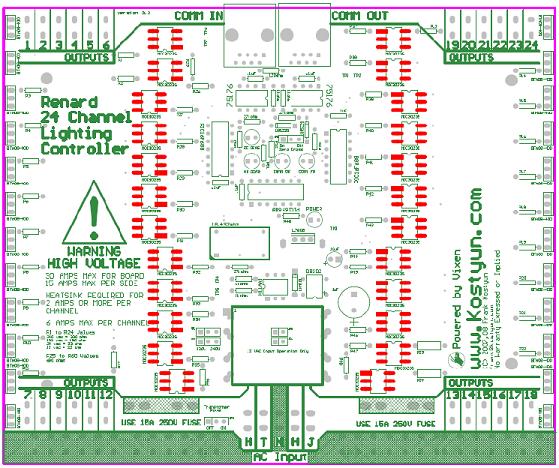
=== Layout === | |||
[[Image:REN_24_25.jpg]] | |||
=== COOP PCB V2.5 === | |||
[[Image:WAITING.jpg]] | |||
=== BOM === | |||
<pre> | |||
PCB | |||
1 TBA Renard 24-Port PCB | |||
511-BTA08-400B 24 | |||
579-PIC16F688-I/P 3 | |||
571-7969494 1 | |||
595-SN75176BP 2 | |||
511-L7805CV 1 | |||
821-DB102G 1 | |||
571-2828376 4 | |||
271-680-RC 24 | |||
532-7136DG 1 | |||
271-180-RC 24 | |||
271-27K-RC 3 | |||
271-1K-RC 4 | |||
571-5564161 2 | |||
271-120-RC 1 | |||
859-MOC3023 24 | |||
625-1N4001-E3 1 | |||
78-1N5239B 2 | |||
838-3FD-310 1 | |||
782-H11AA1 1 | |||
520-TCF1843-X 1 | |||
140-HTRL25V1000-RC 1 | |||
140-HTRL25V10-RC 1 | |||
140-HTRL16V100-RC 1 | |||
</pre> | |||
Revision History | |||
1/20/2007 Initial Design | |||
3/20/2007 Revision 2 submitted to test manufacturing. | |||
7/15/2007 Changed RJ45 to comply with current Renard standards. | |||
7/15/2007 Added additional holes for a larger transformer. | |||
7/15/2007 Added transformer voltage selection jumpers, will allow for 120/240v operation. | |||
7/15/2007 Changed fuse size to 5x20mm fuse from AG3 fuse. | |||
7/16/2007 Added option for DIP or SMT MOC2032 optos. | |||
8/20/2007 Version 2.5 submitted to test manufacturing. | |||
Errata for Rev 1 PCB - | |||
1) Onboard regulator not functioning properly: needed addition of 1000uF capacator. | |||
2) Outputs are out of order. | |||
3) Triacs are located to close together. | |||
Errata for Rev 2 PCB - | |||
1) Outputs 17/18 are swapped. | |||
2) RS485 traces swapped. | |||
Revision as of 05:09, 31 August 2007
Revision 1 board (first revision) Revision 2 board (second revision) Revision 2.5 board (final revision)
Schematic
Media:Renard64_sch_001.pdf (please note, the schematic is identical to the Renard64)
Layout
COOP PCB V2.5
BOM
PCB
1  TBA                   Renard 24-Port PCB

511-BTA08-400B 24
579-PIC16F688-I/P 3
571-7969494 1
595-SN75176BP 2
511-L7805CV 1
821-DB102G 1
571-2828376 4
271-680-RC 24
532-7136DG 1
271-180-RC 24
271-27K-RC 3
271-1K-RC 4
571-5564161 2
271-120-RC 1
859-MOC3023 24
625-1N4001-E3 1
78-1N5239B 2
838-3FD-310 1
782-H11AA1 1
520-TCF1843-X 1
140-HTRL25V1000-RC 1
140-HTRL25V10-RC 1
140-HTRL16V100-RC 1
Revision History
 1/20/2007 Initial Design
 3/20/2007 Revision 2 submitted to test manufacturing.
 7/15/2007 Changed RJ45 to comply with current Renard standards.
 7/15/2007 Added additional holes for a larger transformer.
 7/15/2007 Added transformer voltage selection jumpers, will allow for 120/240v operation.
 7/15/2007 Changed fuse size to 5x20mm fuse from AG3 fuse.
 7/16/2007 Added option for DIP or SMT MOC2032 optos.
 8/20/2007 Version 2.5 submitted to test manufacturing.
Errata for Rev 1 PCB -
 1) Onboard regulator not functioning properly: needed addition of 1000uF capacator.
 2) Outputs are out of order.
 3) Triacs are located to close together.
Errata for Rev 2 PCB -
 1) Outputs 17/18 are swapped.
 2) RS485 traces swapped.
