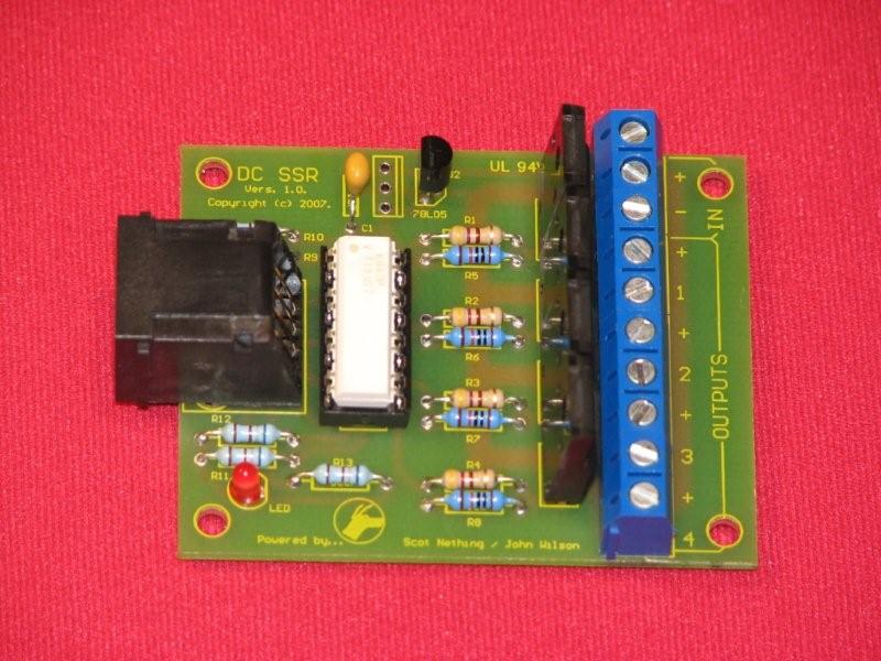
4 Channel DCSSR Assembly Instructions
Background
The DC SSR project was commenced at the request of Scott Nething, who wanted to control some DC Devices for Halloween. We worked on this project and had some prototype boards working for the shows, and I have subesquently tested the DC SSRs with LED MR16s, and dimmed them using PWM code from a RENARD.
Design
The board is a simple design, and follows the standard connection for an AC SSR COOP board. THe RJ45 Socket provided the connection to the Controller. The LED on the board indicates 5VDC is being supplied from the Controller to the OPTO.
The OPTO, which is different to the MCO3023Ms used on the AC SSR, is a K84PH, 16 pin DIP IC. I purchased mine from Mouser. 782-K847PH was the Mouser Part # and they cost $1.02 each, and here is the Datasheet The OPTO provides DC isolation from the Controller to the DC load. this is a safety feature, though some would suggest it could be deleted, I felt that will storms and electrical noise, it makes sense to isolate the PC and controller from the Lights.
The load switching is provided by MOSFETs. Mouser stock these parts, RFD14N05L, as part # 512-RFP14N05L and here is the Datasheet
The
Parts List
 4 MOSFETs  512-RFP14N05L
 1 OPTO 782-K847PH
 5 680 ohm resistors
 4 470 ohm resistors
 4 10k resistors
 1 LED
 1 RJ socket
 1 7805 or 78L05
 5 538-39890-0302 Screw terminals
