16 Channel Renard with SSR Assembly Instructions
Overview
- Assembly Time: 2 hours
- Skill Level: Medium
Disclaimer
ALL INFORMATION WITHIN THIS DOCUMENT IS PROVIDED "AS IS" AND WITHOUT ANY EXPRESS OR IMPLIED WARRANTIES, INCLUDING, WITHOUT LIMITATION, THE IMPLIED WARRANTIES OF MERCHANTABILITY AND FITNESS FOR A PARTICULAR PURPOSE. I DO NOT GUARANTEE ANY INFORMATION IN THIS DOCUMENT IS ACCURATE, AND IT SHOULD BE USED FOR ABSTRACT EDUCATIONAL PURPOSES ONLY.
THIS FILE IS DISTRIBUTED IN THE HOPE THAT IT WILL BE USEFUL, BUT WITHOUT ANY WARRANTY; WITHOUT EVEN THE IMPLIED WARRANTY OF MERCHANTABILITY OR FITNESS FOR A PARTICULAR PURPOSE.
The standard ChristmasWiki Disclaimers also apply.
Reference Material
Tools
- Bench Soldering Iron
- Silver Solder
- Flat cut dykes
- Desoldering bulb
Other Requirements
- You will need an RS232 to RS485 converter. I would suggest EBAY
Related Documents/Links
- RS485 Converter from Ebay
- Parts List
- Theory of Operations
- Image of Board
- Top of PCB
- Botton of PCB
- Silk Screen
- Latest PIC Code
Build Steps
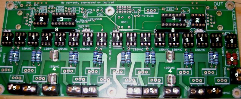
| Install Item | Qty | Mouser P/N | Location | Notes |
|---|---|---|---|---|
| 1. IC sockets 6 pin | 17 | 571-3902611 | U3-U19 | Make sure they are oriented the same way as the silk screen image. U19 is oriented opposite of the others. |
| 2. IC Sockets 8 Pin | 2 | 575-193308 | U20 & U21 | . |
| 3. IC Sockets 14 Pin | 2 | 575-199314 | U1 & U2 | . |
| 4. Bossman Fuse Holder | 4 | 504-1a3399-10 | H1 & H2 pads | Make sure the notch on the fuse holder is oriented so one is on the top and the other on the bottom to properly hold the fuse. |
| 5. Euro Sytle Terminal Blocks | 11 | 538-398890-0302 | Lower Edge of Board | . |
| 6. 15Kohm resistors | 2 | 71-ccf60-15k-e3 | R17 & R18 | . |
| 7. 178ohm resistors | 16 | 273-178-rc | R1 - R16 | Orient the colored bands all the same way for ease of troubleshooting later. |
| 8. 10pin 680ohm bus resistor | 2 | 266-680 | above U7 & U15 | . |
| Numbered Photo - Numbers correspond to the build steps | ||||
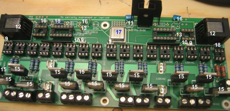
| 9. 2 ping jumper mount | 4 | 571-3-644456-2 | J1 - J4 | . |
| 10. Green LED | 2 | 604-wp7104gt | Ch2Diag #1 & #2 | The short leg of the led goes to the flat side of the silkscreening |
| 11. Monolithic Radial Capacitor | 2 | 81-rpee41h105m4k1e12 | C1 & C2 | . |
| 12. Amp Modular Jacks rj45 | 2 | 571-5520251-4 | Upper Right and Left | . |
| 13. Coated axial ceramic capacitors | 2 | 80-c410c104m5u | C3 & C4 | . |
| 14. Voltage Regulator | 1 | 821-TS7805C2 | 5vReg | . |
| 15. 8 amp Triac | 16 | 511-BTA08-400b | Bottom of board | Be sure to solder these well as they will be carrying 110v A/C |
| 16. 1K ohm resistors | 3 | 660-mf1/4dc1001f | R20, R21 & R24 | . |
| 17. Crystal Clock oscillator | 1 | 520-tck1843-x | OSC1 | . |
| 18. 22k ohm resistor | 3 | 660-mf1/4dlt52r2702f | R19, R22 & R23 | . |
| Numbered Photo - Numbers correspond to the build steps | ||||
| 19. zener diode | 1 | 78-in5239b | D2 | . |
| 20. zener diode | 1 | 512-1n5229b-t50a | D1 | . |
| 21. 120 ohm resistor | 1 | 660-mf1/4dct52r1200f | R26 | . |
| 22. VR/50v diode | 1 | 625-1n4001-e3 | D3 | . |
| 23. red led | 1 | 604-wp7104ec | Top Center | . |
| 24. H11aa1 | 1 | 782-h11aa1 | U19 | . |
| 25. Rs485 | 2 | 837-isl81487eip | U20 & U21 | . |
| 26. Pic Chips | 2 | 11-11 | #2 | . |
| 27. fuses | 2 | 504-gma-5 | H1 & H2 | . |
| 28. Heat Sink | 1 | 532-574502B00 | 5vReg | . |
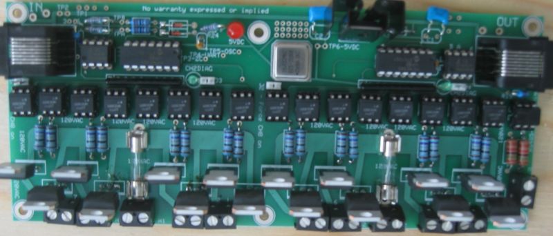
| Here is a picture of the final product | ||||
Options
240 or 24 volt Conversion
The original controller was designed for operation on 110VAC and many of the parts were specified for 110V. The board will operate at other voltages, however a number of changes need to be made.
The first decision to be made is what voltage you want to switch. The triacs are responsible for switching the primary voltage. The is no reason that the primary voltage for the TRIACs could not be 240VAC or 24VAC, however the circuit will need to be modified.
One of the major changes is the ZC detect section of the controller. The original circuit specified a H11AA1 for the optoisolator, with two 15k ohm 1watt resistors for current limiting. Details on the H11AA1 can be found here
I understand that the 15kΩ values are calculated as follows:
I(fwd-peak) = 5mA
V(rms) = 110 VAC RMS
V (peak) = V(rms) * 1.41 = 150VAC
R = V(peak) / I (fwd-peak) = 150V / 0.005 A = 30k ohm Two resistors of 15 k each for a total of 30k.
P = I(peak)(squared) * R = 0.005 * .005 * 15000 / 2 = 0.2W per resistor.
12VDC switching.
12VAC switching.
The peak voltage for a 12 VAC line is 12 x 1.414 = 17 V, so R = 17 V / 1 A = 17 ohms minimum. At 12VAC, rounded to 22 ohms for a standard value.
24VAC switching.
Parts Required and changes.
Gate Resistors - The original value for the gate resistors (item 7) was 180 ohms. For 24VAC operation, the gate resistors need to be changed to 33 ohms.
H11AA1 limiting resistors - These will need to be changed to 3.3k 1/4 watt.
240VAC switching.
Parts Required and changes.
Gate Resistors - The original value for the gate resistors (item 7) was 180 ohms. For 240VAC operation, the gate resistors need to be changed to 360 ohms.
H11AA1 limiting resistors - I am going to make a suggestion for the board to operate on 240VAC that will require a number of physical and electrical changes to the ZC circuit on the controller. This modification is designed to use a low voltage transformer to derive the ZC signal from, instead of the 240VAC Hot rail.
1. Fit two R18s to the PCB. Now that the PCB has been modified, you need to fit two new R18s, appropriate for the ZC voltage the H1AA1 will be sensing.
2. Cutting a track. Looking at the copper side of the PCB, you will notice a small track common from the HOT rail to the inside H1AA11 resistor (R18). There are two R18s, and I'll refer to them as Inside and Outside R18s. The Outside R18 is the one closest to the edge of the PCB. (I'll see if I can take a picture of my board.). By cutting this track, the H11AA1 will be floating with reference to the HOT on the TRIAC (240VAC in this example).
3. Fitting a jumper wire. With the original design, you only needed to connect the White (neutral) to the 2 pole terminal block. The terminal block is located on the right hand side of the PCB, and has a N and and a NC marked on the silkscreen overlay. using a short piece of jumper wire, solder a connection between the NC on the terminal block and the hot side of the Inside R18. This will replace the track you cut in Step 2.
3. Fit two R18s to the PCB. Now that the PCB has been modified, you need to fit two new resistors to the ZC circuit. I am going to use a 30VAC CT transformer to power my board (via a Diode rectifier circuit). Taking a tap from the transformer
Computer feed/power cable
Now you have installed all the parts, the next decision is how you will connect the controller to the PC, and how you will power the board.
The majority of the controller is run from a 5 volt DC regulator that is located on the PCB. The regulator is a 7805, and will provide a regulated 5VDC supply. The input voltage for the controller needs to be at least 9 VDC and no more than 15 VDC.
Checking the datasheet for the 7805, the minimum input voltage must be 2.0V greater than the V(out) = 7.0 V and with the input power diode (1N4001) having a Maximum Instantaneous Forward Voltage Drop of 1.1V, the absolute minimum is 8.1V. However, the system was analyzed with a VOM and a variable output power supply, and to assure 5.0VDC minimum at TP6, it is recommended to stay above 7.5VDC at TP2.


