24 Channel Renard with SSR Assembly Instructions
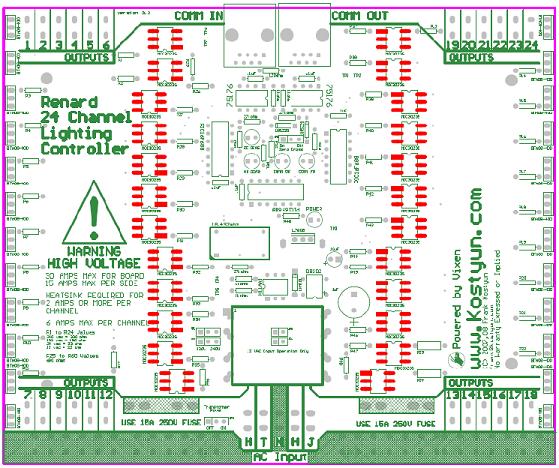
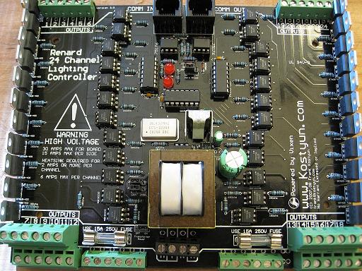
Revision 1 board (first revision) Revision 2 board (second revision) Revision 2.5 board (final revision)
Schematic
Media:Renard64_sch_001.pdf (please note, the schematic is identical to the Renard64)
Layout
COOP PCB V2.5
Co-Op Board 3.0 Assembly Instructions
Currently in-process!
Design Notes for v 3.0 Co-Op Board
No notes yet!
BOM
PCB
1  Ren24v3                             Renard 24-Port PCB

Board Specific Parts:
571-7969494 1
595-SN75176BP 2
511-L7805CV 1
821-DB102G 1                           '''SUB PART 512-DF01M'''
532-7136DG 1
271-27K-RC 3
271-1K-RC 4
271-120-RC 1
625-1N4001-E3 1
78-1N5239B 3
838-3FD-320 1
782-H11AA1 1
520-TCF1843-X 1
140-HTRL25V1000-RC 1
140-HTRL25V10-RC 1
140-HTRL16V100-RC 1
534-3517 4
504-GMA-15 2


Parts from the Common Parts List:
511-BTA08-400B 24
859-MOC3023 24
579-PIC16F688-I/P 3
604-WP63ID 2
604-WP1503GD 1
271-180-RC 24
271-680-RC 28
581-SA105E104MAR 5
571-41032390 1
571-3828115 4
571-1-390261-2 2
571-1-390261-3 3
571-5564161 2

Common Parts Description:
ST Microelectronics BTA08 Triac Driver (24 needed)
MOC 3023 Optocoupler (24 needed)
Microchip PIC 16F1688 (3 needed)
Red T1 3/4 LED (2 needed)
Green T1 3/4 LED (1 needed)
180ohm 1/4 watt resistor (24 needed)
680ohm 1/4 watt resistor (24 needed)
.10 uF Ceramic Capacitor (5 needed)
.100 three pin header (4 needed) Part specified is a 40 pin, cut off size that is needed.
.100 Shunt (4 needed) You may also "steal" these off of old computer parts.
8 pin DIP socket (2 needed)
14 pin DIP socket (3 needed)
RJ45 Sockets (2 needed) orientation doesn't matter. Specified part is same as the Ren64

Parts changed for board 3.0
571-2828376 8 (Four needed for board 2.5) PART OPTION #1 - Screw down Terminal
651-1725041 4 Double Stacked Terminal
534-1287 52 PART OPTION #2 - Spade Terminals
- NOTE UPDATED 10/06 - I put the wrong transformer part # Old part is 838-3FD-310 please see here if you purchased any.
Revision History
 01/20/2007 Initial Design
 03/20/2007 Revision 2 submitted to test manufacturing.
 07/15/2007 Changed RJ45 to comply with current Renard standards.
 07/15/2007 Added additional holes for a larger transformer.
 07/15/2007 Added transformer voltage selection jumpers, will allow for 120/240v operation for our friends down under.
 07/15/2007 Changed fuse size to 5x20mm fuse from AG3 fuse.
 07/16/2007 Added option for DIP or SMT MOC2032 optos.
 08/20/2007 Version 2.5 submitted to test manufacturing.
 10/01/2007 Making small adjustments based on user feedback to ease setup of board. No major changes made.
 01/14/2007 Corrected RS485 pins 4/5 to match Ren16 and Ren64
 01/14/2007 Minor silkscreen corrections.
 01/14/2007 Increase the size of the board to add a neutral buss onto the board.
 01/14/2007 Added support for either spade terminals or screw down terminals.
Errata for Rev 1 PCB -
 1) Onboard regulator not functioning properly: needed addition of 1000uF capacator. (corrected in rev 2.0 board)
 2) Outputs are out of order. (corrected in rev 2.0 board)
 3) Triacs are located to close together. (corrected in rev 2.0 board)
Errata for Rev 2 PCB -
1) Outputs 17/18 are swapped. (corrected in rev 2.5 board)
Errata for Rev 2.5 PCB - (Co-Op Board)
 1) RS485 traces swapped from the Ren16/Ren64 pin config. (To be corrected in Rev 3.0 Board)
 2) Silkscreen needs to have some clarification done for part orientation.
Planned Errata for Rev 3.0 PCB - (Board not yet in production)
2) 24v/36v input voltage support. (This requires more of locating compatable parts)
Design Notes for v 2.5 Co-Op Board
Pin 1 of the crystal is on the bottom left.
Pin 1 of the transformer is on the top left.
The cathode (striped) pin of the 1N4001 diode is on the top.
The correct designation of the capacitor on the top right is .1uF, not .1F.
The + pin of the DB102 is on the bottom right both of the ~ should be on the left.
The parts list has a 100uF cap, ignore it - as its not needed. There is a 1uF on the board, also not needed.
The 7805 (flat side) goes to the top of the board.
The heatsink for the 7805 should be trimmmed at the bottom to allow for proper fit.
The fuse clips are two tight for the board - now sure how this happened - I need to look into this more - as this is the part that I ordered last year and it fits fine.
The jumpers on the board are for 120/240v operation. If you don't plan on using the boards on 120v these can be hard soldered with a jumper wire.
There are two resistors that are close to the output blocks, when installing them, leave them up a bit so they can be pushed back a little bit.
PC to Renard24 Cable
- NOTE this applies to version 2.5.0
The FKostyun Renard24 board has on-board power supply circuitry and on-board zero-crossing circuitry, so all that it needs on the RJ45 cable are data signals and ground. If you are using RS232 input and connecting it directly to the PC serial port, the following cable pinout will work:
PC DB9 Pin 3 to RJ45-pin 5
PC DB9 Pin 5 to RJ45-pins 1,2,4 (pins 1 and 4 are required, pin 2 is optional).
This cable will not work with the Renard16, Renard64 or Ren-C boards because pins 4 and 5 on the Renard24 are reversed from those other boards.

