Renard
Overview
Renard is the name of a computer-controlled, PIC-based dimmer scheme, and also refers to dimming controllers that people have built based on this scheme. The designs all use mid-range PIC micro-controllers, are generally modular in units of eight channels (dimmable circuits), and use medium-speed, daisy-chainable, one-direction serial communications for input. Renard controllers do not have stand-alone show sequencing capabilities, and rely on a separate computer (usually a PC) to send it real-time sequences of dimmer commands.
This design was originally described in the Simple PIC-Based 8-Port Dimmer 'How-To' on the http://computerchristmas.com website in a generic form. Since then various people have designed and built controllers based on this hardware, and there are likely to be coop buys of one or more of these designs. Renard is strictly a DIY, hobbyist effort at this time, with no commercial products available (either software or hardware).
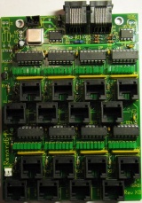
Here is a picture of an assembled Renard8 pcb (an 8-channel board with an RS485 interface). The two connectors in the lower left are for cables that go to remotely located 4-channel SSR boards, and the two on the upper right are for serial (RS485) input and output.


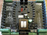
In addition to the Renard8 pictured above, there are several other Renard boards available. These include 16 and 24 channel versions with onboard SSRs, and a 64 channel version without SSRs. In addition, a transformer board exists for providing power and zero-crossing to a Renard, as well as a board to convert an Olsen 595 board to a Renard board. More information can be found on these controllers' respective pages, accessible from the Renard Main Page.
The Pieces and How They Connect Together
Create some drawings.
Distance
The maximum distance between controllers (or between the PC and the first controller) depends on whether RS232 or RS485 is used as the physical communications method. For RS232 the standards only specify short distances (less than 15 m), but past experiences in other situations suggests that it should work up to several times that distance, especially if low capacitance cable is used. For RS485 it should work out to a distance of more than 300m.
Number of Circuits (Channels) per Serial Port
The number of Renard channels that can be supported per serial port depends on both the baud rate and on the frequency of updates that has been programmed into the Vixen sequence. The most common PC control software is Vixen, which easily supports multiple serial ports (including USB-RS232 and USB-485 converters).
| Total Renard Channels Capable for a given Baud Rate/Refresh Interval* | |||
| Baud Rate | Refresh Interval | ||
| 100 ms | 50 ms | 25 ms | |
|---|---|---|---|
| 115200 | 1150 | 574 | 286 |
| 57600 | 574 | 286 | 142 |
| 38400 | 382 | 190 | 94 |
| 19200 | 190 | 94 | 46 |
Note* - these numbers are based on using the Modified Renard Plugin included in Vixen 2.X as the dimmer codes that require two-byte encoding are avoided.
Firmware Versions
There are several different versions of the Renard Firmware available.
The first ('regular') version sends out a 30 uS low-going pulse (about 36 uS in areas with 50 Hz AC power), which is intended just to turn on the SSR at the right point in the AC cycle. This pulse is only long enough to activate the SSR, which then stays on by itself until the end of the AC cycle. The advantage of this version is that it draws the least amount of power from the +5V supply. The disadvantage of this version is that the current draw of AC-powered LED lights may be too low during certain parts of the AC power cycle to allow the opto/triac to stay on by itself. The current draw of each SSR output is about 6 mA, or 48 mA for 8 channels. However, the duty cycle of each SSR input is about 1:256, so the average current draw is about .18 mA (much less than the PIC itself).
The next (PWM) version of the firmware sends out a variable width low-going pulse synchronized to the AC power cycle. The pulse starts at the same time as it would in the 'regular' version of the firmware, but lasts until the end of the AC cycle instead of turning off right away. The advantage of this version is that it can be used for dimming direct-drive LEDs (those without any SSRs involved), and will be better at dimming low-current lights with SSRs (including LED lights intended for AC operation). The disadvantage of this version is that it draws a lot more current from the +5V supply in the worst case. The current draw of each SSR output is still 6 mA (or 12 mA if there are status LEDs in parallel with the SSR), for a total of 48 mA (96 mA). The worst case duty cycle is now 100%, so the full 48 mA (or 96 mA) has to be accounted for.
The last (DC) version of the firmware is very similar to the PWM firmware, also sending out a variable-width pulse. However, this pulse is not synchronized to the AC power line, so there is no need to connect a zero-crossing signal to the controller.
SSR Selection
The Renard Dimmer is designed to turn the SSRs on at different points of each AC powerline cycle (at the beginning for high-brightness, in the middle for medium brightness, and at the end for very low brightness). As a result, the SSRs must be selected for random-phase turn-on. The Renard controllers will not work properly with SSRs designed for zero-crossing turn-on.
Driving LED Light Strings
Controlling LED light strings requires the use of the special version of the firmware designed for PWM operation (as opposed to the standard version of the firmware, which controls the light intensity by pulse positioning). The reason for this is that LED current at certain voltage (brightness) levels may be too low to latch the optos/triacs in the SSRs. The PWM firmware eliminates this problem by driving the SSRs for the entire 'ON' portion of each AC power line cycle, rather than providing just a narrow pulse at the start of the 'ON' period.
Power Requirements
The power requirement for the controller varies with the exact application. The PIC itself usually draws around 5mA. Additional current is required for the oscillator (if present), the serial line interface chips, the SSRs and the voltage regulator (if any). It is hard to give guidelines for these parts, because there are many possible choices for all of these parts. It is best to consult the datasheets for the parts that are actually installed.
Observed Current Draw
The current consumption numbers were obtained by placing a 1 Ω resistor (+/- 5%) in series with the power input pin(s) to the controller, and measuring the voltage across the resistor. The columns with the label 'term' were measurements taken with a 120 Ω termination resistor connected across the RS485 output signals, while 'no term' measurements were taken with the RS485 output connector left open. These numbers should be viewed as representative, not exact. The actual numbers will vary from chip to chip, with temperature, the regulator output voltage, tolerance of the RS485 terminating resistor, and so forth.
| PCB | Non-PWM Current (no term) | Non-PWM Current (term) | PWM Current (no term) | PWM Current (term) |
|---|---|---|---|---|
| Renard8 | 20 mA | 39 mA | 60 mA | 80 mA |
| XMUS 16-Channel | 45 mA | 71 mA | 122 mA | 149 mA |
Note: All measurements taken with the PIC configured to use an external 18.432 MHz oscillator, and with all output channels connected to SSRs (no on/off LED installed on the SSR, however). The outputs of the PIC were configured for maximum dimmer brightness (i.e. worst case situation). The measurements were taken with a DC supply connected to the pins 7,8 on the RJ45 connector, with the zero-crossing signal supplied by other means. In addition, one of the output pins was observed with an oscilloscope to verify correct operation.
Comparison with Other Schemes
LOR AL D-LIGHT DMX-512
Future Directions
Protocol
Version 1
Character Format
Baud Rate can vary, current firmware is programmed for 57600.
1 Start Bit, 8 Data Bits, No Parity bit, 1 Stop bit (8N1)
Special Characters
0x7D - Pad byte, silently discarded by controller firmware, inserted by host PC to prevent Tx overrun
0x7E - Sync byte, start of packet marker.
0x7F - Escape byte, used as prefix for encoding dimmer levels that correspond to the special characters.
To send the value 0x7D as data (rather than as a special character), send the two-character sequence '0x7F-0x2F' in its place.
To send the value 0x7E as data (rather than as a special character), send the two-character sequence '0x7F-0x30' in its place.
To send value 0x7F as data, send the two-character sequence '0x7F-0x31' in its place.
The PICs have a rather large internal clock frequency tolerance, which could cause a transmitter overrun in a PIC which has a slow clock. This could happen under the following circumstances:
1) The host PC is transmitting characters with one stop bit, and
2) One (or more) of the PICs is using its internal oscillator (instead of an external crystal) and
3) That oscillator is running at the low end of it's tolerance (1% slow),
The Renard firmware doesn't have any separate provision for transmit buffer other than the internal PIC transmit buffers. If data is arriving at the PIC faster than it can clear the UART transmitter, some data in the PIC transmitter would be over-written, causing data to be lost. The PAD byte is intended to give the transmitter in a slow PIC time to catch up.
Packet Format
Byte 0 - 0x7E (sync byte)
Byte 1 - Command/address byte (usually 0x80, see below)
Byte 2-n - Dimmer values (0-0xFF, values 0x7D, 0x7E and 0x7F have special encoding, all others are sent raw)
Firmware Operations
When the controller receives a character, it first checks to see if it is the sync character (0x7E). If so, this is the start of a packet, and the controller resets its packet receiving state machine. The controller re-transmits the sync byte, so that down-stream controllers can also reset their packet receiving state machines.
The next character is the command/address byte. There are three possible cases for this byte:
1) If this byte is less than 128 (0x80), it is for some protocol that this firmware cannot handle (reserved for future use). The command/address byte is retransmitted, as are all the remaining bytes in the packet.
2) If the byte is exactly 0x80, the next eight bytes (after decoding) are intended for this controller. The command/address byte is retransmitted. The next eight bytes are decoded and used internally without retransmitting. The remaining bytes in the packet are retransmitted for use by the downstream controllers.
3) If the byte is greater than 0x80, the packet is intended for some downstream controller. The command/address byte is decremented and transmitted, and the remaining bytes in the packet are retransmitted.
Schematic
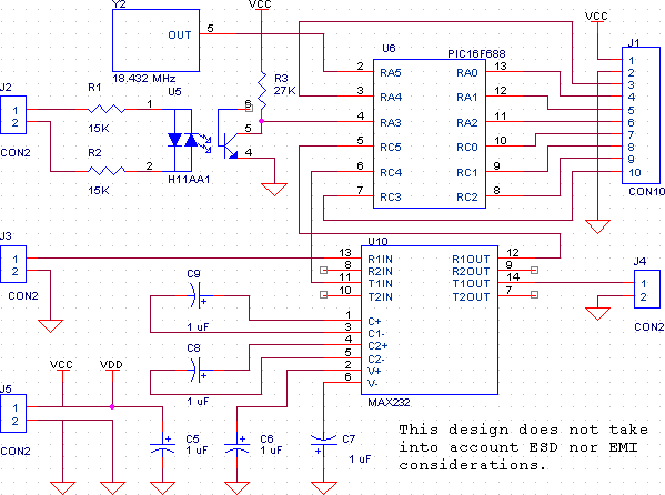
This is a generic Renard schematic, not specific to any particular board. It is intended as the starting point for creating a custom design, and many of the elements of this schematic can be modified for individual circumstances.
AC Input (J2)
This connector is used to bring 110VAC into the board for sensing the AC zero-crossing. The resistors R1 and R2 will need to be changed for operation at other voltages.
High voltage is present on this connector, and great care should taken with this connector and the related components to prevent damage or injury. Do not build this circuit if you are not knowledgeable about working with power-line voltages.
Power Connector (J5)
This is used to provide power (+5V) to the Renard controller.
Serial (RS232) Connectors (J3 and J4)
These connectors are used for input data (J3, from either the PC or an upstream Renard controller) and transmitting data to downstream controllers (J4).
SSR Connector (J1)
This connector is designed to interface with the Simpleio TRIAC8 board. The current firmware versions assume that the SSRs are configured in a current-sink mode. The outputs of the PIC are active low. In the inactive state the outputs are high, and are driven low to activate the SSR. The normal firmware will cause the outputs to driven low for about 30 μS (for 60 Hz operation, slightly longer for 50 Hz operation). This fairly narrow pulse will be latched in both the opto-coupler and the triac in the SSR, extending the cycle until the AC voltage drops back to 0.
In many cases it may be desireable to replace J1 with connectors that are better suited to the particular application.
RS232 Voltage Converter (U10, C8 and C9)
This is the classic MAX232 circuit used for converting between RS232 voltage levels (+/- 15V) and TTL logic levels (0 to 5V). This circuit may be replaced with RS485 interface chips (such as the SN75176 or SN75179) if operation with RS485 is desired.
Firmware
See the Renard Firmware page.

