Beginners Setup Guide The Renard SS16: Difference between revisions
Jump to navigation
Jump to search
No edit summary |
|||
| Line 199: | Line 199: | ||
<li>Install two RS232/RS485 Interface ICs U4 & U5 (PN# 511-ST485BN). | <li>Install two RS232/RS485 Interface ICs U4 & U5 (PN# 511-ST485BN). | ||
<br> | <br> | ||
<br> | |||
<br> | <br> | ||
::If you have a PIC programmed with the [[Renard Firmware#Beta Diagnostic Firmware | Renard Diagnostic Firmware]] continue with step 43. | ::If you have a PIC programmed with the [[Renard Firmware#Beta Diagnostic Firmware | Renard Diagnostic Firmware]] continue with step 43. | ||
<br> | <br> | ||
::If you only have PICs programmed with [[Renard Firmware#Regular Firmware | Renard Operational Firmware]] then go to step 60. | ::If you only have PICs programmed with [[Renard Firmware#Regular Firmware | Renard Operational Firmware]] then go to step 60. | ||
<br> | |||
<br> | <br> | ||
<li>Install PIC microcontroller U6 (PN# 579-PIC16F688-I/P) programmed with the [[Renard Firmware#Beta Diagnostic Firmware | Renard Diagnostic Firmware]]. | <li>Install PIC microcontroller U6 (PN# 579-PIC16F688-I/P) programmed with the [[Renard Firmware#Beta Diagnostic Firmware | Renard Diagnostic Firmware]]. | ||
<li>Place a shunt (jumper) on JP3. | <li>Place a shunt (jumper) on JP3. | ||
| Line 221: | Line 217: | ||
<li>Turn ON AC power | <li>Turn ON AC power | ||
<li>The [[Renard Firmware#Beta Diagnostic Firmware | Renard Diagnostic Firmware]] should perform the following channel test: | <br> | ||
<br> | |||
<span style="color:#D2691E"> | |||
<blockquote> <center>'''NOTE:''' <br> | |||
'''The following step only applies if you are using the [[Renard Firmware#Beta Diagnostic Firmware | Beta Renard Diagnostic Firmware]].''' | |||
<br> | |||
'''If you are using the proven/existing [[Renard Firmware#Diagnostic Firmware | Renard Diagnostic Firmware]] just skip this step.'''</center></blockquote> | |||
</span> | |||
<br> | |||
<li>The [[Renard Firmware#Beta Diagnostic Firmware | Beta Renard Diagnostic Firmware]] should perform the following channel test: | |||
:*All channels ON for approx. 2 seconds | :*All channels ON for approx. 2 seconds | ||
:*All channels OFF for approx. 2 seconds | :*All channels OFF for approx. 2 seconds | ||
Revision as of 23:57, 25 March 2009
Introduction
- This page was created to help out the new users who aren't fully confident that they have built their Renard SS16 board correctly. These steps are designed to allow the user to test/verify most components in a manner that should help to eliminate the possibility of damaging any of the components during initial testing.
- The following procedures may appear to be tedious and time consuming but they are here for the individuals who are not confident in their soldering skills. By following these steps, the individual will be able to test out individual components and signal paths to verify that everything is working properly.
- The following procedures require the individual to be familiar with the operation of a digital multimeter (or voltmeter/ohmmeter if you prefer). If you currently do not know how to measure resistance or how to measure voltage, please take some time now an learn these basic skills before attempting these procedures. This website provides some basic information on using multimeters.
| All DC voltages in this document are referenced to GND. So for all measurements, the multimeter negative (-), usually black, lead needs to be connected to a GND point on the PCB. The best location would be the GND Test Point located below U1. The positive lead (+), usually red, gets connected to the location called out in the procedure. |
Disclaimers
- Due to the nature of the information contained on this page, it is imperative that all individuals read and understand the disclaimers contained here.
Renard SS16 Basic Setup Steps
- Ensure all power is OFF
- Remove all cables
- If installed, remove all 21 removable IC chips (U2, U4 thru U7, and M1 thru M16).
- Perform a complete and thorough inspection of the underside of the PCB.
- Check all the solder pads for clean solder joints, no bridging between adjacent pads and that all pads did get soldered.
- Make sure the board surface is clean and free from any debris and flux residue.
- If not installed already, install an appropriate rated fuse in the left side fuse holder. Use the smallest value fuse that you have available for this portion of testing.
- Using a smaller fuse here is for safety during initial power testing. If there are any problems with bad triacs, bridged solder pads or a bad transformer during first power application, a small fuse will blow before any permanent damage to the PCB can occur.
- Connect an AC power cable to the left side [N 120V] terminal block. The 120V neutral line (wide blade on a polarized plug) goes to the N terminal and the 120V hot line goes to the 120V terminal.
- Turn ON AC power
- Measure DC voltage at the +5 test point (below U1).
- It should be 5.0 (+/- .5) VDC
- If incorrect , then go to the Renard SS16 Troubleshooting Guide
- Power LED should be lit.
- If it didn’t , then go to the Renard SS16 Troubleshooting Guide
- Place a shunt (jumper) on JP3.
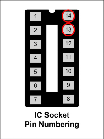
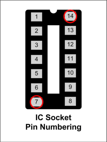
- Momentarily connect a jumper (small piece of wire) between U6 IC socket pin 13 and pin 14
- HB LED should light
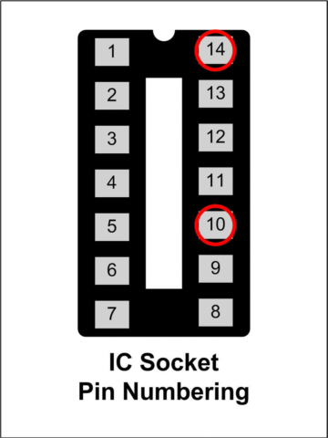
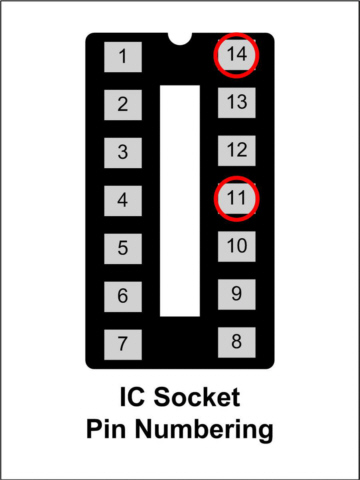
- Momentarily connect a jumper between U6 IC socket pin 10 and pin 14
- ZC LED should light
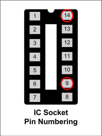
- Momentarily connect a jumper between U6 IC socket pin 9 and pin 14
- SD LED should light
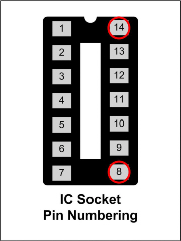
- Momentarily connect a jumper between U6 IC socket pin 8 and pin 14
- FE LED should light
- Momentarily connect a jumper between U6 IC socket pin 7 and pin 14
- OE LED should light
- If any of the LEDs in steps 11 thru 15 did not light, then go to the Renard SS16 Troubleshooting Guide
- Remove the shunt from JP3.
- Turn OFF AC power
- Install optoisolator M1 (PN# 859-MOC3023)
- Attach some test lights to the [N Ch1] terminal block
- If you installed a small value fuse in step 5, replace it with an appropriate value fuse in the left side fuse holder.
- The fuse needs to be rated to handle the load of the lights that will be connected to channels 1 thru 8 but not greater than 15 amps.
- Turn ON AC power
- Test lights should be OFF
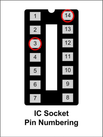
- Momentarily connect a jumper (small piece of wire) between U6 IC socket pin 3 and pin 14
- Test lights should come ON when the jumper is connected
- If either step 23 or step 24 failed, then go to the Renard SS16 Troubleshooting Guide
- Repeat steps 18 thru 25 using the information in the following table:
Optoisolator Test Lights at
Terminal BlockConnect jumper between M2 [N Ch2] M3 [N Ch3] M4 [N Ch4] M5 [N Ch5] M6 [N Ch6] M7 [N Ch7] M8 [N Ch8]
- Turn OFF AC power
- Connect an AC power cable to the right side 120V terminal block. The 120V neutral line (wide blade on a polarized plug) goes to the N terminal and the 120V hot line goes to the 120V terminal. This connection can be either a separate power cord or it can just be a jumper from the left side 120V terminal block.
- If not installed already, install an appropriate value fuse in the right side fuse holder.
- The fuse needs to be rated to handle the load of the lights that will be connected to channels 9 thru 16 but not greater than 15 amps.
- Make sure the AC power cable going to the left side 120V terminal block is still securely attached.
- Turn OFF AC power
- Install optoisolator M9 (PN# 859-MOC3023)
- Attach some test lights to the [N Ch9] terminal block
- Turn ON AC power
- Test lights should be OFF
- Momentarily connect a jumper (small piece of wire) between U7 IC socket pin 3 and pin 14
- Test lights should come ON when the jumper is connected
- If either step 35 or step 36 failed, then go to the Renard SS16 Troubleshooting Guide
- Repeat steps 31 thru 37 using the information in the following table:
Optoisolator Test Lights at
Terminal BlockConnect jumper between M10 [N Ch10] M11 [N Ch11] M12 [N Ch12] M13 [N Ch13] M14 [N Ch14] M15 [N Ch15] M16 [N Ch16]
- Turn OFF AC power
- Place a shunt on JP2
- Install optocoupler U2 (PN# 782-H11AA1).
- Install two RS232/RS485 Interface ICs U4 & U5 (PN# 511-ST485BN).
- If you have a PIC programmed with the Renard Diagnostic Firmware continue with step 43.
- If you only have PICs programmed with Renard Operational Firmware then go to step 60.
- Install PIC microcontroller U6 (PN# 579-PIC16F688-I/P) programmed with the Renard Diagnostic Firmware.
- Place a shunt (jumper) on JP3.
- If desired, attached lights to terminal blocks [N Ch1] thru [N Ch8]. The diagnostics can be done with only the on-board LEDs.
- Turn ON AC power
NOTE:
The following step only applies if you are using the Beta Renard Diagnostic Firmware.
If you are using the proven/existing Renard Diagnostic Firmware just skip this step.
- The Beta Renard Diagnostic Firmware should perform the following channel test:
- All channels ON for approx. 2 seconds
- All channels OFF for approx. 2 seconds
- Channel 1 turns ON for approx. 1 second then turns OFF
- Channel 2 (HB LED) turns ON for approx. 1 second then turns OFF
- Channel 3 turns ON for approx. 1 second then turns OFF
- Channel 4 turns ON for approx. 1 second then turns OFF
- Channel 5 (ZC LED) turns ON for approx. 1 second then turns OFF
- Channel 6 (SD LED) turns ON for approx. 1 second then turns OFF
- Channel 7 (FE LED) turns ON for approx. 1 second then turns OFF
- Channel 8 (OE LED) turns ON for approx. 1 second then turns OFF
- The above routine is done three times
- The above routine is done three times
- The Renard Diagnostic Firmware should now be blinking the HB LED (channel 2) and ZC LED (channel 5). All other channels/LEDs should be OFF.
- If either step 47 or step 48 failed, then go to the Renard SS16 Troubleshooting Guide
- Turn OFF AC power
- Connect a data cable to the computer running Vixen to either J2 or JDP1 on the Renard SS16.
- If receiving RS232 data from the computer place a shunt on JP1
- Turn ON AC power
- Wait for the diagnostics routine in step 47 to complete
- Run a Vixen sequence
IMPORTANT REMINDER: Vixen only sends out data when there is a change in event data. So make sure that the test sequence you are using has frequent changes in the event data.
- SD LED will be ON whenever Vixen sends data to the Renard SS16. The FE and OE LEDs should remain OFF.
- If incorrect , then go to the Renard SS16 Troubleshooting Guide
- Turn OFF AC power
- Remove U6
- To verify another functional PIC, repeat steps 43 thru 58 with a new PIC
- Install PIC microcontrollers U6 & U7 (PN# 579-PIC16F688-I/P) programmed with the Renard Operational Firmware.
- Turn ON AC power
- Run a Vixen sequence
- If the outputs do not respond correctly, then go to the Renard SS16 Troubleshooting Guide