DirkCheapSSR
What is it?
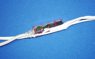
The DirkCheapSSR is a very small, 4-channel SSR that has a maximum current capacity of 1 amp per channel. It is intended to be built directly into a display piece and is small enough to be built directly into the wiring and covered with shrink-tube. The original project arose in May 2012 and included a group buy.
Assembly
Notes
NOTE: These assembly directions are based on the PDF dated 20120509
DANGER - USE CAUTION. This is a circuit board that connects directly to 120vac electrical current, which can be dangerous or even lethal. If you are not comfortable working with 120vac, consider asking for assistance in assembling and testing this SSR.
This guide outlines one way to assemble the SSR; you may decide on a different way. In any event, read these instructions completely through before starting assembly. In addition to the circuit board and component parts, you will need the following tools and/or supplies to assemble this SSR:
- Wire trimmer/cutter
- Soldering iron and solder
- Electrical Tape or Shrink tubing (both large and small)
- A length of cat5 cable
- 4 strings of lights
- 2 zip ties (optional)
- Heat gun or other heat source (if using shrink tube)
Instructions

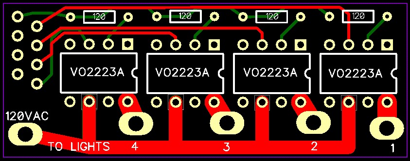
- 1. Install the four 680 ohm resistors first. The board is marked 120 for that is the minimum resistor value to use. There is no special orientation to the resistors but they should lie flat against the circuit board. Solder them into position and clip off the extra leads. NOTE: Resistors with values between 120 and 1000 ohms will work with the DirkCheapSSR. The resistor lowers the trigger current for the LED in the VO2223A chip. The 680 ohm resistor causes a source current draw of approximately 5ma; using a higher-value resistor will lower the current draw while 120ohms will raise it to the maximum allowed, approximately 10ma. Be sure to use a resistor that lowers the current draw enough so that when all the controller’s channels are on, the total of all SSRs don’t draw more current than the controller’s electronics can provide. Either 1/8 or 1/4 watt resistors will work fine.
- 2. Solder the four VO2223A chips into place, following the orientation of the dot/notch on the chip. On the DirkCheapSSR board, the square pin is for pin #1 of the VO2223A chip. Note: The chip is a little sensitive to heat, so don’t overdo the soldering. It is certainly permissible to solder 8-pin DIP sockets in place instead of the VO2223A chips themselves and then insert the chips into the DIP sockets. In addition to adding assembly cost, this will raise the profile of the finished board, possibly making it more difficult to slip a piece of heat-shrink tube over it. The benefit of DIP sockets, of course, is the ease of replacing a VO2223A chip should replacement become necessary.
- 3. Clip off the power plugs from the 4 sets of lights this SSR is to control. Then solder a single wire from each of the intended four light strings into their respective channel holes, marked 1-2-3-4 on the board. Note the order of the channels has channel 1 as the far right hole.
- 4. Strip off a 1” section of insulation from each the remaining wires of the four light strings. Lightly twist the four wires together temporarily but do not solder.
- 5. If you are planning to cover the whole SSR with a large section of shrink tube, slide it over the four joined wires; slide it far enough so you have some working room. Do not heat yet.
- 6. Slide another length of heat shrink tube (smaller diameter this time) over and past the twisted junction. Be sure the length is long enough to completely cover the twisted wires with room to spare on each side. Do not heat yet.
- 7. Strip off a 1” section of insulation from one of the wires coming from the fused power plug of one of the strings of lights. Twist this wire with the other four twisted wires and solder them together. There should be five wires connected when done. Slide the smaller shrink tube back over the soldered junction so the junction is completely covered, then heat the tube to shrink it over the joined and soldered wires.
- 8. Solder the unconnected wire from the plug to the SSR hole marked 120VAC.
- 9. Trim a 1/4” of insulation off each of the 8 wires in a piece of cat5 wire. We suggest using stranded cat5 cable as it bends more easily and can withstand flexing better than solid copper, but if the SSR is to be permanently mounted, solid cat5 wire will work fine. The cat5 wires will be soldered into the 8 holes (in RJ45 layout format) on the far left side of the SSR. It’s true that only 5 of those wires are needed, but soldering all 8 wires will add strength to the connection and we suggest soldering all 8. NOTE: Pin 1 of the connection is the hole that is closest to the upper left corner of the SSR board; the orange/white wire should be soldered into pin 1. From top to bottom, the rightmost pins (closer to the VO2223a chip) are pins 2-4-6-8 and should be soldered as follows:
- Pin 2/hole 2 – solid orange wire
- Pin 4/hole 4 – solid blue wire
- Pin 6/hole 6 – solid green wire
- Pin 8/hole 8 – solid brown wire
- The other holes are for the blue/white, green/white and brown/white wires and it doesn’t matter which goes where since there is no connection to them on the SSR board.
- 10. At this point, all holes on the SSR board should have something soldered into them except for one hole on the right side of each VO2223A chip – which is blank. Double-check all solder joints and clip off any extraneous solder or wire leads. If any of the solder points are exceptionally sharp, you may consider touching them up with the soldering iron and a bit more solder so they aren’t sharp enough to poke through the shrink tubing later on.
- 11. Trim the cat5 wire to the length of your choice and Install a cat5 plug onto the end using the normal wiring scheme (typically the category 5 “B” wiring scheme).
- 12. Slide the large piece of shrink tube down over the entire SSR, but don’t heat it yet. This is only for temporary protection and testing.
- 13. Now you may test the SSR. IMPORTANT: WHEN PLUGGED IN, THE SSR IS CARRYING DANGEROUS ELECTRICAL CURRENT. DO NOT PICK UP OR HANDLE THE BOARD IN ANY WAY WHEN IT IS PLUGGED INTO 120VAC POWER!
- 14. If testing is successful, unplug the SSR from both power and the controller. For additional cord strength, you may wish to add a zip tie around the cables at each end; binding them together usually gives them more strength.
- 15. Be sure the shrink tube completely covers the SSR and apply heat to finish it up. NOTE: You may wish to insert some caulking, silicone sealant or other sealant into the ends of the shrink tube just before heating and sealing it. The caulking will go a long way to making the SSR more weatherproof, if not completely waterproof.
Options
- An RJ45 jack can certainly be soldered onto the board in place of soldering the cat5 wire directly to the board. Before soldering the jack, consider where the SSR will be mounted – it could make a difference as to whether you choose to use a vertical or horizontal RJ45 jack.
- You can use a wire nut to connect the five common A/C wires although this method may not be as strong as soldering them together and covering the junction with insulation or shrink tube.
- The A/C traces on the SSR board are on both the top and bottom. BE EXTREMELY CAREFUL IF YOU PLUG THIS SSR INTO 120VAC WHEN IT IS NOT COVERED WITH SOME ELECTRICAL PROTECTION, AND ABOVE ALL, DO NOT HANDLE THIS BOARD WHEN IT IS PLUGGED INTO 120VAC POWER!
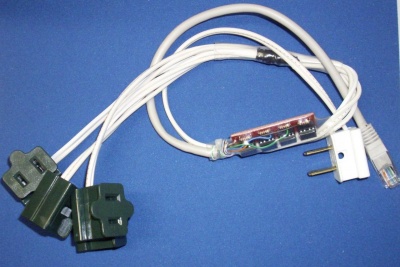
- Instead of connecting the SSR directly to light strings, you may choose to make it into a sort of “dongle” with 4 plugs on one end; the power plug and cat5 connection on the other. If so, just remember to incorporate a fuse somewhere on the power input wire for protection. Here’s a sample dongle that was made with the prototype DirkCheapSSR:
How Many Lights Can the DirkCheapSSR take?
The “stress chart” to the right outlines the load a single VO2223A chip can accommodate before it fails, and you may think that multiplying it times 4 (because there are 4 chips on the board) is the maximum. No. Our recommendation is not to exceed 2/3 (.66) amp of current on any one channel and not more than 3 amps for the entire board. DirkCheapSSR was designed for LOW current applications and if you need to control a great many lights, we suggest using one of the other readily available SSRs that are designed for higher current capacities.
Other Links
- VO223A Datasheet
- PDF version of these directions: http://doityourselfchristmas.com/wiki/images/f/fe/DirkCheapSSR_technical.pdf
- Threads discussing using a VO2223A and MOC devices for low cost, low current SSRs: http://doityourselfchristmas.com/forums/showthread.php?20414-Low-Amp-SSR
- Brilliant Build Idea in PVC by boyelroy11: http://doityourselfchristmas.com/forums/showthread.php?20664-My-DirkCheap-SSR-Build


