LEDancer
General
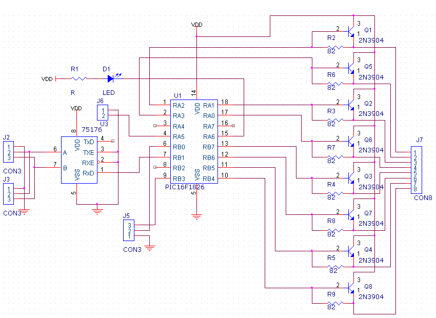
The LEDancer (Le Dancer) is an inexpensive controller for up to 56 LEDs with a DMX512 input interface. The LEDs are connected together in a Charlie-Plexed common-cathode configuration. The design needs to use 2N3906 booster transistors for the LED cathodes to ensure that the low-level drive of the PIC is not exceeded, a configuration sometimes called chipi-plexing. The DMX address of the controller can be changed by shunting one of the PIC pins to ground and then sending a specially formatted DMX packet with the desires address.
PCB Schematic
This is a generic LEDancer schematic, useful as the basis of a PCB design. Some of the necessary details (such as a DC regulator) have been omitted from the schematic, but should be included in most PCB designs.
PCB Design
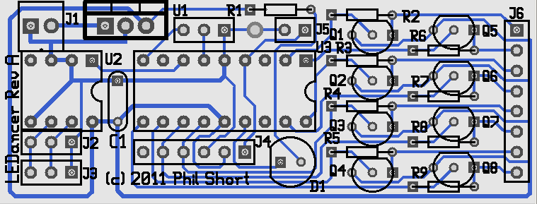
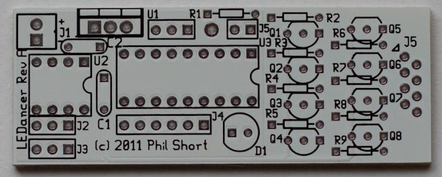
At the moment there isn't a released PCB design. The design consists of a controller board (with a PIC16F1826 and a ST485 RS485 receiver, a jumper for enabling the DMX Address Program Mode, eight resistors and 8 2N3904 transistors, and some connectors.
Here is a proposed sample PCB design (note that it still needs caps next to the Voltage Regulator):
Video
Click here for a demo video of the LEDancer
Connector Pinout
Jumper Identification
BOM - Bill Of Materials
Mouser
| Mouser PN | Description | Qty |
| 538-22-03-2021 | Headers & Wire Housings VERT PCB HDR 2P TIN PLATING | 2 |
| 538-22-03-2061 | Headers & Wire Housings VERT PCB HDR 6P TIN PLATING | 1 |
| 538-22-03-2031 | Headers & Wire Housings VERT PCB HDR 3P TIN PLATING | 3 |
| 80-C322C104K5R | Multilayer Ceramic Capacitors (MLCC) - Leaded 50volts 0.1uF 10% X7R | 1 |
| 80-C322C334M5U5CA | Multilayer Ceramic Capacitors (MLCC) - Leaded 50volts 0.33uF 20% Z5U | 1 |
| 299-82-RC | Carbon Film Resistors - Through Hole 82ohms 5% | 8 |
| 512-2N3904TA | Transistors Bipolar (BJT) NPN Transistor General Purpose | 8 |
| 511-ST485BN | Buffers & Line Drivers Hi-Spd Lo Pwr Trans | 1 |
| 579-PIC16F1826-I/P | Microcontrollers (MCU) 3.5KB Flash 256 byte 32 MHz Int. Osc | 1 |
| 571-1-390261-2 | IC & Component Sockets 8P ECONOMY TIN | 1 |
| 571-1-390261-5 | IC & Component Sockets 18P ECONOMY TIN | 1 |
| 604-WP7104GT | Standard LED - Through Hole GREEN TRANSPARENT | 1 |
| 299-330-RC | Carbon Film Resistors - Through Hole 330ohms 5% | 1 |
LEDs
In addition, you will need up to 56 White Piranha Style Super flux LEDs. Other colors could be used, but you may need to adjust the resistor values on the controller board.
=BOM==
LED Segment PCBs
LED Connections
THIS SECTION IS OUT OF DATE.
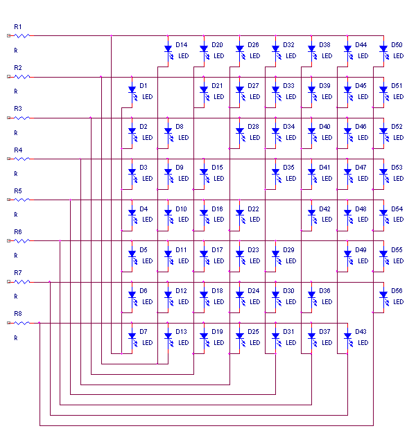
The LEDs can either be hand-wired on some sort of substrate (perhaps some plexiglass or linoleum), or a PCB can be designed to hold the LEDs. In all of the following diagrams LED1 is the LED controlled by the lowest DMX address, LED2 is next, and so forth. LED56 is the LED controlled by the highest (56'th) DMX address.
Schematic
Wirelist
Output1,LED1-C,LED2-C,LED3-C LED4-C,LED5-C,LED6-C,LED7-C,LED14-A,LED20-A,LED26-A,LED32-A,LED38-A,LED44-A,LED50-A
Output2,LED1-A,LED8-C,LED9-C,LED10-C,LED11-C,LED12-C,LED13-C,LED14-C,LED21-A,LED27-A,LED33-A,LED39-A,LED45-A,LED51-A
Output3,LED2-A,LED8-A,LED15-C,LED16-C,LED17-C,LED18-C,LED19-C,LED20-C,LED28-C,LED8-A,LED34-A,LED40-A,LED46-A,LED52-A
Output4,LED3-A,LED9-A,LED15-A,LED22-C,LED23-C,LED24-C,LED25-C,LED26-C,LED27-C,LED28-C,LED35-A,LED41-A,LED47-A,LED53-A
Output5,LED4-A,LED10-A,LED16-A,LED22-A,LED29-C,LED30-C,LED31-C,LED32-C,LED33-C,LED34-C,LED35-C,LED42-A,LED48-A,LED54-A
Output6,LED5-A,LED11-A,LED17-A,LED23-A,LED29-A,LED36-C,LED37-C,LED38-C,LED39-C,LED40-C,LED41-C,LED42-C,LED49-A,LED55-A
Output7,LED6-A,LED12-A,LED18-A,LED24-A,LED30-A,LED36-A,LED43-C,LED44-C,LED45-C,LED46-C,LED47-C,LED48-C,LED49-C,LED56-A
Output8,LED7-A,LED13-A,LED19-A,LED25-A,LED31-A,LED37-A,LED43-A,LED50-C,LED51-C,LED52-C,LED53-C,LED54-C,LED55-C,LED56-C
Stackable LED Board Design
Here is the schematic for a practical stackable board design. By connecting eight of these boards together (output to input, pin-1 to pin-1, etc) the previous schematic/wirelist can be readily built.
Assembly Instructions
PIC Program
Here is the first version of the firmware. It uses an LED arrangement that is slightly different from the one documented above, so it won't be particularly useful. It is, however, the latest version that has been tested on hardware, so it is included here for reference.
Here is a second version of the firmware, modified to use the actual LED arrangement described earlier in this document. This is untested, however, because the author hasn't built the LED hardware yet that corresponds to the description above.
Here is a third version. The only changes from the second version are comments, particularly the hardware mapping list near the start of the file.
Here is the fourth version. It has changes to accommodate the current LED board revision, which is a common anode design rather than the original common-cathode design. It also has related changes to remove some ghosting issues.
Programming the DMX Address
To program the DMX address, first format (using Vixen) a DMX packet with the MSB of the address in the first byte of the packet and the LSB in the second byte. Then, install the jumper J5 (in the PCB layout above), and set up Vixen to send out the DMX packet with the new address. When the controller has accepted the new address and stored in the EEPROM, the first seven LEDs will come on and stay on solid. In order to resume normal operation you need to remove the jumper J5 and cycle power on the controller off and on.
Video
Click here for a demo video of the LEDancer


