Power Pops Fanout - 1 Input with 4 Outputs: Difference between revisions
Ukewarrior (talk | contribs) Created page with "work in progress" |
Ukewarrior (talk | contribs) No edit summary |
||
| Line 1: | Line 1: | ||
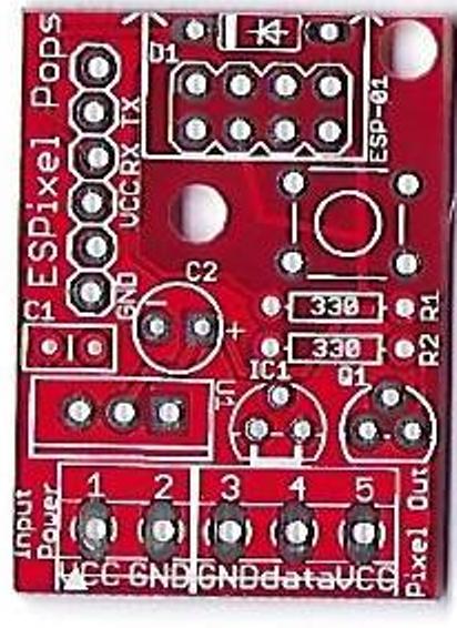
[[Image:Pixel_Pops_Picture_x2.jpg|right|Version V2]] | |||
=='''This page is under construction'''== | |||
==The ESPixel Pops is a variation of the original ESPixel Stick by Bill Porter== | |||
<p> | |||
The genesis of the ''pixel stick'' controllers started with designs by Bill Porter. | |||
You can read about this at Bills website found at: [http://www.billporter.info/ The mind of Bill Porter] | |||
<br> | |||
<br> | |||
The ESPixel Pops is the most basic of the Pixel Stick designs. It is a fully through hole PCB with no smd(surface mount) components. Therefore, it is easily built by most anyone with basic soldering skills. | |||
This variation was created by Pops Jones (ukewarrior) in order to create a form factor that would fit inside a 1" thin wall PVC tube. | |||
<br> | |||
<br> | |||
From a software perspective, it is an E1.31 sACN (Streaming ACN) pixel controller that connects over a standard (802.11g/n) WiFi network. The firmware is open source and developed in the ESP8266 Arduino environment. It provides a web based configuration front-end and currently supports WS2811 / WS2812 pixels. (3-wire pixels) | |||
<br> | |||
</p> | |||
<p> | |||
== General Features == | |||
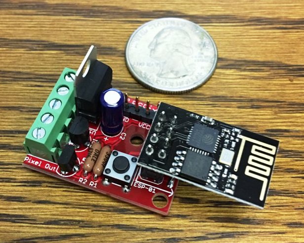
[[Image:Built_unit_with_quarter_for_scale.jpg|right|small]] | |||
</p><p> | |||
'''The Pixel Pops has these main features''' </p><p> | |||
'''1. It supports 3 wire pixels such as those based on 2811, 2812 and GECE chipsets'''</p><p><br> | |||
'''2. It runs as a wireless E 1.31 datastream from your main controller (aka show computer)'''</p><p><br> | |||
'''3. It utilizes the ESP-01 module for processing and wireless operation''' | |||
<br><br> | |||
'''4. It supports both 5v and 12v pixels''' | |||
<br><br> | |||
'''5. The board is small enough to fit inside a 1" thinwall PCB pipe with the board measuring only 24.18x33.32 mm. This type of pipe is listed as SDR-21. Lowes example: [https://www.lowes.com/pd/Charlotte-Pipe-1-in-x-10-ft-200-Sdr-21-PVC-Pipe/1000080801 Thin all 1" PCV pipe]'''<br> | |||
The board is professionally manufactured with 1oz copper and the holes are through plated. This makes for easy and more error free soldering.</p><p> | |||
All wires attach via terminal blocks. However, the use of terminal blocks is optional as the holes support direct soldering of wires. | |||
<br> | |||
'''The Schematic can be downloaded by clicking on this link: | |||
[[Media:ESPixel_PopsSchematic.pdf]] | |||
. | |||
== Order your own boards == | |||
You can order your own boards with the information given below, or you can contact: ''ukewarrior'' on the DIYC forum to see if he has any in stock. | |||
The PCB industry has a standard for the definition of a PCB. It's called a 'gerber' file. | |||
This is a set of files that have the actual instructions that tell the machines how to operate. | |||
The Gerbers for the ESPixel Pops are found at this link: (link below is incorrect, file to be posted) | |||
[http://doityourselfchristmas.com/forums/dynamics/attachment.php?attachmentid=416&d=1333648310 Zip File containing the SSRneon-G2-LED Gerber files] | |||
This is all your should need to order PCBs from any PCB manufacturer. | |||
== Fuses == | |||
There is no onboard fuse for the ESPixel Pops. | |||
</p><p> | |||
Since there is no onboard fuse, if a power overload should occur, the ESP-01 or the ESPixel Pops board may be damaged. | |||
You can add an inline fuse if desired with the input power feed. | |||
</p><p> | |||
== Disclaimers == | |||
'''USE the ESPixel Pops board at Your Own Risk !'''</p> | |||
'''The ESPixel Pops board has NO warranty expressed or implied''' | |||
<p> | |||
== BOM - Bill of Materials == | |||
The BOM contains these generically described parts: | |||
- One ESP8266-01, this is not so much a part, but a complete subassembly.<br> | |||
- One diode. This must be: 1N4148<br> | |||
- One female socket header, 2 rows of pins, 4 pins in each row. This functions as the socket where you plug the ESP8266 module into<br> | |||
- One six pin header. Readily available 2.54mm (.1") pitch. (distance between the pins)<br> | |||
- One tactile switch. 6mm x 6mm. Also readily available. These often have choices as to the height of the push button.<br> | |||
- Two 1/8W or 1/4W carbon film or metal film resistors. 330 Ohms. | |||
- One polarized Electrolytic capacitor. Any value from 10uF to 220uF will do. 10V or above. Pay special attention to the diameter and spacing of the leads. The diameter can be no more than 5mm and the leads should be spaced at 2mm.<br> | |||
- One MLCC monolithic capacitor. 2.54mm lead spacing. 0.1uF, any voltage over 24V. (Usually these are 50V rated) These are typically the 'yellow blob' style capacitors, verses the ones that are shaped like a flat disk. These do NOT have a + & - indication, unlike the electrolitic capacitor noted above.<br> | |||
- One 3.3v voltage regulator. This must be: LD1117V33, which has a TO-220 style package.<br> | |||
- One 5.0v voltage regulator. This part is optional and should only be installed if you are planning to drive 12v pixels.<br> | |||
- One Mosfet. This must be: 2N7000, which has a T0-92-3 style package<br> | |||
- A five pin screw terminal header. 5 positions total. This connection should have 3.81 spacing of the mounting pins.<br> | |||
== Construction Information == | |||
[[Image:Built_unit_with_quarter_for_scale.jpg|left|Version V2]] | |||
<br><br><br><br><br><br><br><br><br><br><br><br><br><br><br><br><br><br> | |||
The ESPixel Pops is a pretty easy build. The real trick is deciding how you plan to power your pixels as that will affect what you do with the board wiring. | |||
== Wiring The ESPixel Pops == | |||
Along the bottom of the board are 5 connection points. (as viewed from the top...) | |||
The two on the left are for input power. | |||
The three on the right are for pixel connection. | |||
You can either solder on a terminal block or directly solder your wires to the board, or do a mix ! | |||
The Terminal block has 3.81mm hole spacing. (The more common 5mm terminal blocks would have made the board too wide) | |||
Revision as of 23:28, 20 August 2017

This page is under construction
The ESPixel Pops is a variation of the original ESPixel Stick by Bill Porter
The genesis of the pixel stick controllers started with designs by Bill Porter.
You can read about this at Bills website found at: The mind of Bill Porter
The ESPixel Pops is the most basic of the Pixel Stick designs. It is a fully through hole PCB with no smd(surface mount) components. Therefore, it is easily built by most anyone with basic soldering skills.
This variation was created by Pops Jones (ukewarrior) in order to create a form factor that would fit inside a 1" thin wall PVC tube.
From a software perspective, it is an E1.31 sACN (Streaming ACN) pixel controller that connects over a standard (802.11g/n) WiFi network. The firmware is open source and developed in the ESP8266 Arduino environment. It provides a web based configuration front-end and currently supports WS2811 / WS2812 pixels. (3-wire pixels)
General Features

The Pixel Pops has these main features
1. It supports 3 wire pixels such as those based on 2811, 2812 and GECE chipsets
2. It runs as a wireless E 1.31 datastream from your main controller (aka show computer)
3. It utilizes the ESP-01 module for processing and wireless operation
4. It supports both 5v and 12v pixels
5. The board is small enough to fit inside a 1" thinwall PCB pipe with the board measuring only 24.18x33.32 mm. This type of pipe is listed as SDR-21. Lowes example: Thin all 1" PCV pipe
The board is professionally manufactured with 1oz copper and the holes are through plated. This makes for easy and more error free soldering.
All wires attach via terminal blocks. However, the use of terminal blocks is optional as the holes support direct soldering of wires.
The Schematic can be downloaded by clicking on this link:
Media:ESPixel_PopsSchematic.pdf
.
Order your own boards
You can order your own boards with the information given below, or you can contact: ukewarrior on the DIYC forum to see if he has any in stock.
The PCB industry has a standard for the definition of a PCB. It's called a 'gerber' file. This is a set of files that have the actual instructions that tell the machines how to operate.
The Gerbers for the ESPixel Pops are found at this link: (link below is incorrect, file to be posted) Zip File containing the SSRneon-G2-LED Gerber files
This is all your should need to order PCBs from any PCB manufacturer.
Fuses
There is no onboard fuse for the ESPixel Pops.
Since there is no onboard fuse, if a power overload should occur, the ESP-01 or the ESPixel Pops board may be damaged. You can add an inline fuse if desired with the input power feed.
Disclaimers
USE the ESPixel Pops board at Your Own Risk !
The ESPixel Pops board has NO warranty expressed or implied
BOM - Bill of Materials
The BOM contains these generically described parts:
- One ESP8266-01, this is not so much a part, but a complete subassembly.
- One diode. This must be: 1N4148
- One female socket header, 2 rows of pins, 4 pins in each row. This functions as the socket where you plug the ESP8266 module into
- One six pin header. Readily available 2.54mm (.1") pitch. (distance between the pins)
- One tactile switch. 6mm x 6mm. Also readily available. These often have choices as to the height of the push button.
- Two 1/8W or 1/4W carbon film or metal film resistors. 330 Ohms.
- One polarized Electrolytic capacitor. Any value from 10uF to 220uF will do. 10V or above. Pay special attention to the diameter and spacing of the leads. The diameter can be no more than 5mm and the leads should be spaced at 2mm.
- One MLCC monolithic capacitor. 2.54mm lead spacing. 0.1uF, any voltage over 24V. (Usually these are 50V rated) These are typically the 'yellow blob' style capacitors, verses the ones that are shaped like a flat disk. These do NOT have a + & - indication, unlike the electrolitic capacitor noted above.
- One 3.3v voltage regulator. This must be: LD1117V33, which has a TO-220 style package.
- One 5.0v voltage regulator. This part is optional and should only be installed if you are planning to drive 12v pixels.
- One Mosfet. This must be: 2N7000, which has a T0-92-3 style package
- A five pin screw terminal header. 5 positions total. This connection should have 3.81 spacing of the mounting pins.
Construction Information

The ESPixel Pops is a pretty easy build. The real trick is deciding how you plan to power your pixels as that will affect what you do with the board wiring.
Wiring The ESPixel Pops
Along the bottom of the board are 5 connection points. (as viewed from the top...) The two on the left are for input power. The three on the right are for pixel connection.
You can either solder on a terminal block or directly solder your wires to the board, or do a mix ! The Terminal block has 3.81mm hole spacing. (The more common 5mm terminal blocks would have made the board too wide)