Renard 16 Controller
NOTE
This is not the Renard SS16, the popular 16 Channel Controller that is sold in the group buys. For information about that board go to Renard SS16 Controller Board.
Disclaimers
- The standard disclaimers pertaining to the information contained on this wiki page are listed here.
Introduction
- The Renard 16 is a PIC microcontroller based Christmas light controller with 16 solid state relay circuits incorporated into the board. Dave Johnson (xmus) designed the board based on the PIC-based 8-port dimmer concept originally developed by Phil Short. Information on the original concept can be viewed here. Generinc information pertaining to current Renard designs (including maximum channel count) can be found on the Renard wiki page.
- A lot of great information on the Renard 16 can be found on Dave Johnson’s website located here. The manual that Dave put together is very informative and a must read for anybody wanting to use the Renard 16. This wiki page is not intended to replace Dave’s manual but is instead meant to present the basic info necessary to get a Renard 16 up-and-running.
- This wiki page is a complete overhaul of previous Renard 16 wiki pages. This page has replaced the previous pages not simply modified them. The previous wiki pages are still available here and here.
- NOTE: Most references in this wiki are made to the Renard 16 Version 1.9.1 pcb.
The Board
Circuit Diagram
- A schematic diagram can be found here.
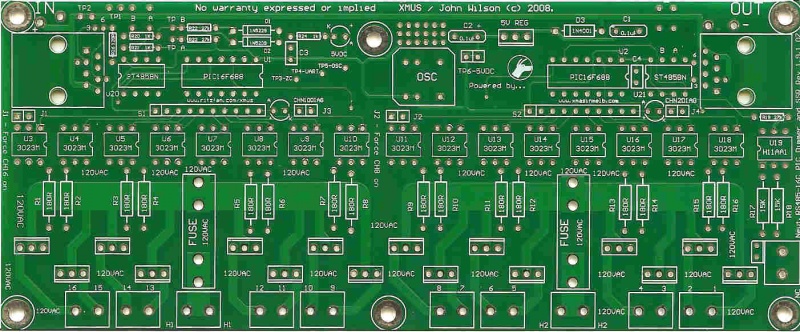
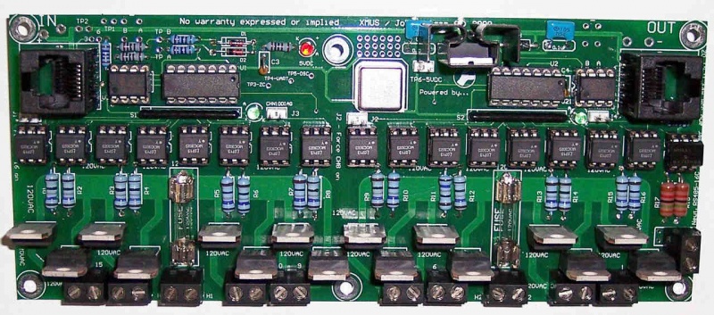
Key circuit components
Connectors
- IN – RS232/RS485 incoming data and 12 VDC input
- OUT – RS485 outgoing data and 12 VDC passed thru.
IC Chips
- U1 & U2 – PIC16F688 Microcontrollers
- U3-U18 – MOC3023 Optoisolator
- U19 – H11AA1 Optocoupler, used to generate the Zero Cross signal
- U20 & U21 – ISL81487, RS232/RS485 Receiver/Transmitter
Resistors
- R1-R16 – Triac gate resistors. The value of these resistors will vary depending of which Triacs are being used and what line voltage is being switched. For the Triac from the BOM, use these values:
- 115/120 VAC operation – Use 180 ohm resistors
- 240 VAC operation – Use 330 ohm resistors
- 24 VAC operation – Use 33 ohm resistors
- For other voltages, check this DIYC thread for more info on how to calculate the correct value.
- R1-R16 – Triac gate resistors. The value of these resistors will vary depending of which Triacs are being used and what line voltage is being switched. For the Triac from the BOM, use these values:
Diagnostic LEDs
- CHN10DIAG – This LED is intended for use during troubleshooting of the PIC. When U1 is programmed with the diagnostics firmware and a jumper is placed on J3, the LED will blink on/off to indicate that the PIC is operating correctly.
- CHN2DIAG – This LED is intended for use during troubleshooting of the PIC. When U2 is programmed with the diagnostics firmware and a jumper is placed on J4, the LED will blink on/off to indicate that the PIC is operating correctly.
- 5VDC – Lit whenever the voltage regulator is generating 5 VDC.
Other Components
- OSC – ECS-2100AX-18.432MHZ, 18.432 MHz Crystal Clock Oscillator
- 5V REG – TS7805CZ, 5 VDC Voltage Regulator
- D8-D23 (not referenced as such on silkscreen) – BTA08-400B Triacs
Jumpers
- J1 [Force CH16 ON] – When a shunt is installed, a ground is applied to Pin 2 of optoisolator U3. This will cause the channel 16 triac to turn on. This is helpful when trying to isolate a problem to the PIC or to the optoisolator/triac section.
- J2 [Force CH8 ON] – When a shunt is installed, a ground is applied to Pin 2 of optoisolator U11. This will cause the channel 8 triac to turn on. This is helpful when trying to isolate a problem to the PIC or to the optoisolator/triac section.
- J3 – When a shunt is installed and PIC U1 is programmed with the diagnostics firmware, the CHN10DIAG LED will blink on/off to indicate that the PIC is operating correctly. When PIC U1 is programmed with the operational firmware (PWM mode), the CHN10DIAG LED turns on/off at the same time as channel #10.
- J4 – When a shunt is installed and PIC U2 is programmed with the diagnostics firmware (PIC U1 must have operational firmware), the CHN2DIAG LED will blink on/off to indicate that the PIC is operating correctly. When PIC U2 is programmed with the operational firmware (PWM mode), the CHN2DIAG LED turns on/off at the same time as channel #2.
Test Points
- TP1 – Ground
- TP2 – VCC, the DC voltage you are supplying to the Renard16
- TP3 ZC – Zero Cross signal
- TP4 UART – Data signal going from PIC U1 to PIC U2
- TP5 OSC – Crystal oscillator output
- TP6 5VDC – Output from voltage regulator, should be +5 VDC
- TPA – Incoming RS485A(+) signal or GND when receiving RS232 data
- TPB – Incoming RS485B(-) signal or RS232 data
Firmware
- The PICs (U1 & U2) must be programmed with the latest firmware for the Renard 16 to operate properly. The firmware can be found here.
Modes of Operation
16 Channel Mode
- A fully populated Renard 16 board will operate in the 16 channel mode without any changes required. The only thing that must be remembered is that the output terminals are not numbered in the same order as the channel order that Vixen will send the data. Vixen channels 1-8 correspond to output terminals 9-16 and Vixen channels 9-16 correspond to output terminals 1-8.
8 Channel Mode
- If the need arises, the Renard 16 board can be operated as an 8 channel controller and still pass along Vixen channel data to the next controller. Do the following for 8 channel controller operation:
- Do not connect any incoming AC voltage to terminal H1 only connect incoming AC to terminal H2. Power must come in on H2 to allow for the creation of the Zero Cross signal.
- Remove U1 and place a jumper from U1 pin 5 to U1 pin 6
- When operating as an 8 channel controller, the output terminals 1-8 will correspond to Vixen channels 1-8.
Data Connection
Typical data cable for Renard 16 hookup
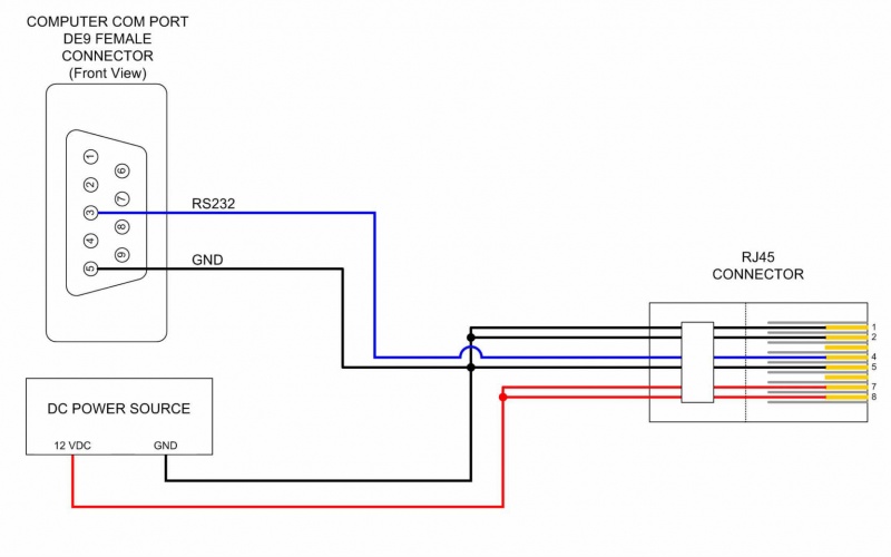
PC DE9 Pin 3 to RJ45-pin 4
PC DE9 Pin 5 to RJ45-pin 5 and pin 1 and/or pin 2
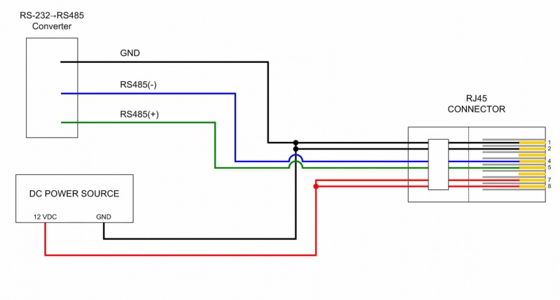
Data cable for Renard 16 hookup using a RS232→RS485 converter:
Due to the many different types of RS232→RS485 converters available the drawing only refers to the signals coming from the converter. Check the documentation for your converter to figure out how/where to hook up the correct wires.
RS485(-) Signal to RJ45-pin 4
RS485(+) Signal to RJ45-pin 5
Powering the Renard 16
- Input power requirements: 8-35 VDC and an AC source
DC power:
- The Renard 16 generates the 5 VDC on-board that it needs for IC chip operation. To create this 5 VDC, there must be a voltage of 8-35 VDC applied to the board. The most commonly used voltage is 12 VDC since it is readily available via computer power supplies.
Connection:
- Typically, the input DC power will come in via RJ45 IN connector pins 7 & 8 with GND (Return) coming in on pins 1 & 2. An alternate method is to connect the incoming DC voltage to TP2 and the GND to TP1.
AC Power:
- The Renard 16 requires AC power for the SSR (opto/triac) circuitry and for generation of the Zero Cross signal. The AC power used will depend on location and the desired application. The parts identified in the BOM are based on using 120 VAC, so if you intend on using a different voltage make sure that know which components will need to be changed.
Connection:
- The incoming “hot” AC lines are connected to terminals H1 and H2. The incoming neutral AC line must be connected to the Neut terminal and not to the NC terminal.
AC Power Handling Capability
Max Input Load
- Each fuse protected bank of eight triacs on the Renard 16 can handle up to 15 amps of current. This limitation is due to the terminal blocks being used, as they are rated at 15 amps. Also you must repair the break on the bottom trace for H1 for that bank to be able to handle that much current safely. Instructions for this can be found here.
Triac Loads
- Based on the pcb trace widths, each triac can handle up to 4 amps of current. A heat sink is highly recommended when running more than about 2 amps thru any triac. Care must be taken to ensure that the total load of the eight triacs in each bank does not exceed the rating of the fuse protecting the triac bank or 15 amps (whichever is less).
Fuses
- When each fuse protected bank of triacs has its own dedicated AC input, the size of the fuse cannot exceed the current handling capability of the input wire or 15 amps (whichever is less).
- If both banks of triacs are being powered by the same AC input and a jumper is running between them, then the size of both fuses added together cannot exceed the current handling capability of the input wire.
Hooking Up the Renard 16
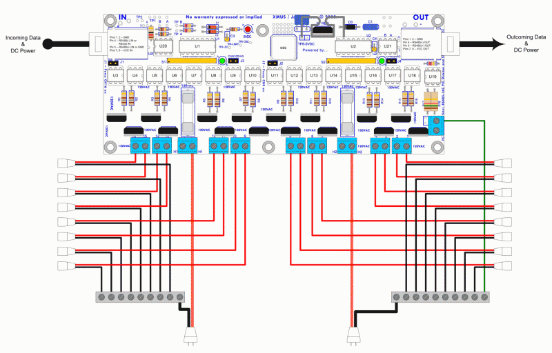
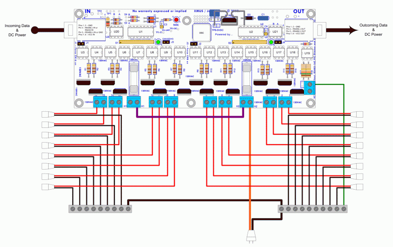
- In the above layout, each bank of triacs has its own dedicated AC input (orange wires). Each bank of triacs could handle up to 15 amps of current as long as the AC input wires could handle that much current and each fuse was the appropriate size.
- In the drawing, all the neutrals are connected together via a bus bar similar to that found in household circuit breaker panels. You can use any method you want to connect the neutrals together but they must all be connected to the main input neutral.
- In the above layout, both banks of triacs are powered by the same AC input (orange wires). Key things to remember in this layout are:
- The size of the left fuse cannot exceed the current handling capability of the purple wire or 15 amps (whichever is less).
- The size of both fuses together cannot exceed 15 amps or the current handling capability of the AC input (orange wire).
- In the drawing, all the neutrals are connected together via a bus bar similar to that found in household circuit breaker panels. You can use any method you want to connect the neutrals together but they must all be connected to the main input neutral.
Computer Setup
VIXEN Settings
- The Renard 16 requires the Renard Dimmer or Renard Dimmer (modified) Plug-In.
- Renard Dimmer Plug-In Settings:
- Protocol Version: 1
- COM1 (or whichever COM port you are connected to)
- Baud: 57600
- Parity: None
- Data bits: 8
- Stop bits: One
- Hold port open during the duration of the sequence execution: Checked
- Renard Dimmer Plug-In Settings:
Relationship between VIXEN Channels and Renard 16 terminals
- Ver 1.9 Boards
- Vixen channels 1-8 correspond to the left hand side terminals 1-8
- Vixen channels 9-16 correspond to the right hand side terminals 1-8
- Ver 1.9 Boards
- Ver 1.9.1 Boards
- Vixen channels 1-8 correspond to terminals 9-16
- Vixen channels 9-16 correspond to terminals 1-8
- Ver 1.9.1 Boards
Related Links
Renard 16 PCB Assembly Instructions
Original Concept of the PIC-Based Dimmer
