Ren64TW: Difference between revisions
Jump to navigation
Jump to search
| Line 19: | Line 19: | ||
==='''Board Availability'''=== | ==='''Board Availability'''=== | ||
:The Ren64TW is currently under development and not available at this time. | :The Ren64TW is currently under development and not available at this time. | ||
:Inquires should be directed to [http://doityourselfchristmas.com/forums/member.php?5150-bolwire bolwire] here on the DIYC forum. | |||
:PCBs should be expected to be available no earlier than June, however if that changes I will update as needed. | |||
==='''Bill of Materials'''=== | ==='''Bill of Materials'''=== | ||
Revision as of 17:22, 3 March 2014
Ren64TW - in development.
This wiki page is under development, please check back as I will be updating it as time allows.
Introduction
- The Ren64TW is a 64 channel board, using external SSRs. It has an on board power supply, and optional XBee support.
- This board is currently in development by J. Bolding (bolwire). An initial run of 10 pcbs has been ordered for testing and verification.
Disclaimers
The Board
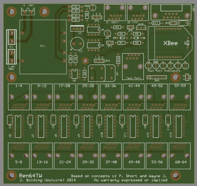
- The board measurement is 5.825"W X 5.500"H, and the provided mounting holes are placed to align with a CG-1500 demarcation enclosure.

Board Availability
- The Ren64TW is currently under development and not available at this time.
- Inquires should be directed to bolwire here on the DIYC forum.
- PCBs should be expected to be available no earlier than June, however if that changes I will update as needed.
Bill of Materials
- The BOM project at Mouser contains all parts needed, except the optional XBee module.
- You can find the Mouser project BOM here
PART NUMBER
(Mouser PN#)QTY REF NOMENCLATURE 511-L4941BV 1 U1 LDO Voltage Regulators 5.0V 1.0A Positive 534-3517 2 F1 Fuse Clips PC FUSE CLIP 5 MM 534-3527C 1 F1 Vinyl Fuse Cover 504-GMA-1-1/2 1 F1 Cartridge Fuses 250VAC 1.5A Fast Acting 511-1N5817 4 D1-4 Diode Vr/20V Io/1A 291-750-RC 2 R1-2 Resistor - 750ohms 1/4W 5% 291-120-RC 1 R3 Resistor – 120ohms 1/4W 5% 299-1K-RC 2 R4, R7 Resistor – 1K ohms 1/8 W 5% 299-27K-RC 3 R5, R8-9 Resistor – 27k ohms 1/8 W 5% 299-680-RC 2 R6, R10 Resistor – 680 ohms 1/8 W 5% 299-33-RC 1 R11 Resistor – 33 ohms 1/8 W 5% 264-330-RC 1 RN1 Resistor Network 6 pin 330 ohm 1/8 w 2% 838-3FS-412 1 TF1 Power Transformer 12.6VAC CT 6.0VA Single Primary 571-7969492 1 120V N Power Terminal 78-1N5229B 1 D5 Diode, Zener 4.3V .5W 78-1N5239B 1 D6 Diode, Zener 9.1V .5W 78-1N5226B 1 D7 Diode, Zener 3.3V .5W 511-L4931CZ33-AP 1 U14 LDO Voltage Regulators 3.3V 0.25A Positive 571-1-390261-3 8 U6-13 14 Pin IC Socket 571-1-390261-2 2 U4-5 8 Pin IC Socket 571-1-390261-1 1 U2 6 Pin IC Socket 571-5556416-1 19 J1-2, SSR Ports RJ 45 Top Entry 649-10090099-S094VLF 1 JDP1 DB 9 Right Angle 815-ACH-18.432-EK 1 U3 Oscillator 511-ST485BN 2 U4-5 ST485BN 604-WP710A10IT 1 PWR Standard LEDs - Through Hole Red 60mcd 625nm 60 deg Transparent 604-WP710A10GT 6 +5 GND 1 2 3 4 Standard LEDs - Through Hole Grn 60mcd 568nm 34 deg Transparent 782-H11AA1 1 U2 Transistor Output Optocouplers Bi-Directional Input 140-REA332M1CBK1325P 1 C1 Aluminum Electrolytic Capacitors - Leaded 16V 3300uF 20% 12.5x25mm 140-REA470M1CBK0511P 1 C2 Aluminum Electrolytic Capacitors - Leaded 16V 47uF 20% 5x11 mm 80-C322C104K5R 9 C3-11 Multilayer Ceramic Capacitors MLCC - Leaded 50volts 0.1uF 10% X7R 579-PIC16F688-I/P 8 U6-13 8-bit Microcontrollers - MCU 7KB 256 RAM 12 I/O 538-22-03-2021 4 JP1-2, JP4-5 Header 2P 538-22-03-2031 2 JP3, JP6 Header 3P 151-8000-E 6 Jumpers 2 POS Shunt 532-577102B00 1 U1 Heatsink M22-7131042 2 Xbee Xbee header
Board Assembly
Jumper Configuration
- The Ren64TW has a jumper for just about any configuration you would like to use.
- Jumper JP1 & JP2:
- For RS-232 (direct to PC) JP1 ON/JP2 OFF
- For RS-485 (output from renard board or converter/adapater) JP1 OFF/JP2 ON, Try removing JP2 if communication issues occur.
- Jumper JP3: Selects weather the incoming data is from a wired connection of XBee module
- Jumper JP4: Enables XBee transmit
- Jumper JP5: Resistor for XBee incoming data
- Jumper JP6: Selects the standard renard method of passing data to the next controller, or to use bypass (thru) for DMX and Start Address firmware use