REN 32 Controller Board
(Redirected from Ren 32)

Introduction
- The REN 32 is the latest 32 channel Microchip 16F688 based PIC microcontroller Christmas light controller that can be used with up to 32 AC or DC solid state relay () . The board design is based on the PIC-based 8-port dimmer concept originally developed by Phil Short. Information on the original concept can be viewed here. Generic information pertaining to current Renard designs (including maximum channel count) can be found on the Renard wiki page. It is capable of running on either 115vac or 230vac main power to the board.
- This controller follows the Renard Standardized Series (SS) controller design: a design effort to standardize the board layouts for Renard based systems and to establish a standardized list of components to use in Renard designs. Some of the goals of the Renard SS design effort were:
- Completely self-contained controller board. All that is needed to start using the board is a data input and an AC power source. No external DC voltage supply or externally generated ZC is needed.
- Common part list used for all boards. There are no special parts for any individual board, all the boards use the same components. The only thing different is the quantity used on each board.
- Common component layout on the board. With only a few exceptions, all the components on the boards are laid out in the same fashion.
- On-board LEDs for full support of Renard diagnostics firmware.
- Easier for a new member to build. By removing extra options from the board, now a member can just order the parts from the BOM and will be able to build the board without having to figure out which options/parts apply to their configuration.
- Easier to support. By having all the boards using the same parts and having the same component layout, it will be easier to provide support to DIYC members when they have problems or ask questions.
- Complete documentation. In the past, boards were created, designed, produced and distributed without much documentation to support them. Documentation was an afterthought and was slow to catch up, some never did or is hard to understand for new members. In the Renard SS design effort, the documentation was created at the same time as the boards so that when the boards were ready for release, the documentation was also ready.

Disclaimers
The standard disclaimers pertaining to the information contained on this wiki page are listed here.
THIS WIKI PAGE IS NOT COMPLETE YET.
The Board


Board Availability
The PCB is available from DIYLEDExpress.com as well as a PCB/BOM Kit.
Circuit Diagram
- The schematic diagram can be found HERE
Key circuit components
- Connectors
| Connectors | ||
| Connector | Type | Function |
|---|---|---|
| J1 | RJ45 | RS485 outgoing data |
| J2 | RJ45 | RS232/RS485 incoming data |
| J3 | RJ45 | Control Signal to SSR Channels 1-4 |
| J4 | RJ45 | Control Signal to SSR Channels 5-8 |
| J5 | RJ45 | Control Signal to SSR Channels 9-12 |
| J6 | RJ45 | Control Signal to SSR Channels 13-16 |
| J7 | RJ45 | Control Signal to SSR Channels 17-20 |
| J8 | RJ45 | Control Signal to SSR Channels 21-24 |
| J9 | RJ45 | Control Signal to SSR Channels 25-28 |
| J10 | RJ45 | Control Signal to SSR Channels 29-32 |
| AC Power In | Screw Terminals | AC Power Feed |
- IC Chips
| Integrated Circuits | |||
| Location | Pins | Type | Function |
|---|---|---|---|
| U1 | 3 | LF50CV | Voltage Regulator |
| U2 | 6 | H11AA1 | Optocoupler, used to generate the Zero Cross signal for ACSSRs |
| U3 | 4 | ECS-2100AX-18.432MHZ | 18.432 MHz Crystal Clock Oscillator |
| U4 | 8 | ST485BN | RS485 Transmitter |
| U5 | 8 | ST485BN | RS232/RS485 Reciever |
| U6 | 14 | PIC16F688 | Microprocessor that controls Channels 1-8 |
| U7 | 14 | PIC16F688 | Microprocessor that controls Channels 9-16 |
| U8 | 14 | PIC16F688 | Microprocessor that controls Channels 17-24 |
| U9 | 14 | PIC16F688 | Microprocessor that controls Channels 24-32 |
- Diagnostic LEDs
- NOTE: The following Diagnostic LEDs will only function when a jumper is placed on JP3 and U6 has the diagnostic firmware loaded.
- Diagnostic LEDs
| Diagnostic LED Feedback | ||
| LED | Firmware in U6 | |
| Diagnostic Firmware |
Operational Firmware | |
|---|---|---|
| POWER | Lit whenever the voltage regulator is generating 5 VDC. | Lit whenever the voltage regulator is generating 5 VDC. |
| HB | will blink ON/OFF to indicate that the PIC is operating correctly | will be ON whenever channel 2 is ON |
| ZC | will blink ON/OFF to indicate that the Zero Cross signal is getting to the PIC correctly | will be ON whenever channel 5 is ON |
| SD | will be ON whenever the PIC is receiving data correctly | will be ON whenever channel 6 is ON |
| FE | will only be ON when the PIC has identified a Framing Error while receiving data | will be ON whenever channel 7 is ON |
| OE | will only be ON when the PIC has identified an Overrun Error while receiving data | will be ON whenever channel 8 is ON |
- Jumpers
- JP1 – RS232 signal ground. Install a shunt (jumper) on JP1 when receiving RS232 data.
- JP2 – 120 ohm termination resistor enable. Normally a shunt will be installed on JP2 when receiving RS485 data. Remove the shunt if you are experiencing problems with incoming data.
- JP3 – Diagnostic LEDs enable. Install a shunt on JP3 to allow the Diagnostic LEDs to function. During normal operation, you can remove the shunt with no negative impact on board operation.
- Jumpers
- Main Voltage – You must provide either a jumper across the 2 horizontal jumpers to enable the board to run on 115vac, or one jumper across the 230vac jumper to allow the board to run on 230vac.
- Test Points
- +5 – Output from voltage regulator, should be +5 ± 0.1 VDC
- GND – Ground
- ZC – Zero Cross signal
- Test Points
Firmware
- The PICs (U6,U7 U8& U9) must be programmed with the correct firmware for the board to operate correctly. There are two types of firmware available: Operational and Diagnostic. The Operational firmware is what you need for normal board operation. The Diagnostic firmware is a troubleshooting aid to use when there are problems with the board.
- Renard SS Operational Firmware:
- Renard SS Operational Firmware.asm – source code that needs to be compiled
- Renard SS Diagnostic Firmware:
- Renard SS Diagnostic Firmware.asm – source code that needs to be compiled
- DMX Firmware:
- Since there are many options available with the Renard DMX firmware it is impractical to post a dedicated Renard SS board version here. Users desiring to use DMX should get the firmware here.
Powering the REN 32
- Input power requirements: An AC source. The board can be powered be either 115vac or 230vac depending on the Main Power Jumper settings.
DC power:
- The Ren32 generates all the DC voltage that it requires on-board and no external DC voltage source is required.
AC Power:
- The REN 32 requires AC power for generation of the DC voltage, the off board SSR (opto/triac) circuitry and for generation of the Zero Cross signal.
AC Power Handling Capability
Maximum Input Load
- Since the REN 32 uses off board SSRs, the power the board can control is based on their capabilities. See the DCSSR and the ACSSR wiki for possible ssr designs to use with this board. Since the REN 32 is actually 4 banks of 8 channels you can mix and match both AC and DC SSRs in groups of 8. All channels in a bank must be the same type (AC or DC).
Fuses
- The board has a safety fuse for protecting the ac mains voltage on the board.
- The BOM calls for a 1 amp fuse.
Hooking Up the REN 32
J1 and J2-Renard Input and Output
The two RJ45 Connectors J1&J2 near the top right of the board are used to bring data signals to and from the board. J1 on the left side is the signal input from the PC or previous Renard controller. J2 on the right side is the output to be daisy-chained to the next Renard controller. The pins on these connectors are used as follows:
| Serial Data Connector Pin Assignments | ||
| Pin # | RJ45 Connector | |
| J1 Input | J2 Output | |
|---|---|---|
| 1,2 | GND | GND |
| 3 | Pin 3 is tied to J2 Pin 3 | Pin 3 is tied to J1 Pin 3 |
| 4 | Data- (Rx) | Data- (Tx) |
| 5 | Data+ (Rx) | Data+ (Tx) |
| 6 | GND | GND |
| 7,8 | Pins 7&8 are tied together to J2 Pins 7&8 | Pins 7&8 are tied together to J1 Pins 7&8 |
Data Connections

Data Cables
- Data cables for Renard SS board hookup directly to computer COMM port

| PC Serial Port to REN 32 Adapter Cable | ||
| RS232 Pin # | ||
| REN 32 RJ45 | ||
|---|---|---|
| PC DE9 Pin 3 | RJ45 Pin 4 | |
| PC DE9 Pin 5 | RJ45 Pin 5 and Pin 1 and/or Pin 2 | |
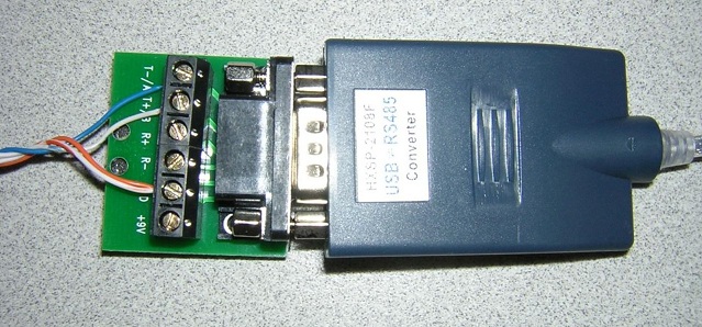
- Data cable for Renard SS board hookup using a RS232->RS485 or a USB->RS485 converter
- Due to the many different types of RS232->RS485 and USB->RS485 converters available, the drawing only refers to the signals coming from the converter. Check the documentation for your converter to figure out how/where to hook up the correct wires. An example is shown here with the HXSP-2108F Adapter Hook-up

| RS485 Dongle to REN 32 Adapter Cable | ||
| RS485 Pin # | ||
| REN 32 RJ45 | ||
|---|---|---|
| RS485(-)/T-/D-/B/485- | RJ45 Pin 4 (blue CAT5 wire) | |
| RS485(+)/T+/D+/A/485+ | RJ45-pin 5 (blue/white CAT5 wire) | |
| GND | RJ45-pins 1 & 2 (orange and orange/white CAT5 wires) | |
- Data cable for Renard SS board hookup in a DMX environment
_to_Renard_SS_Connection.jpg)
| DMX using XLR Connectors Adapter Cable | ||
| DMX XLR Pin # | ||
| REN 32 RJ45 | ||
|---|---|---|
| XLR connector Pin 1 (GND) | RJ45-pin 1 and/or pin 2 | |
| XLR connector pin 2 (Data-) | RJ45-pin 4 | |
| XLR connector pin 3 (Data+) | RJ45-pin 5 | |
_to_Renard_SS_Connection.jpg)
| DMX using RJ45 Connectors Adapter Cable | ||
| DMX RJ45 Pin # | ||
| REN 32 RJ45 | ||
|---|---|---|
| RJ45 connector pin 1 (Data+) | RJ45-pin 5 | |
| RJ45 connector pin 2 (Data-) | RJ45-pin 4 | |
| RJ45 connector pins 7 & 8 (GND) | RJ45-pins 1 & 2 | |
- Data cable for Renard SS board hookup to other Renard boards

Generally only a regular straight-thru CAT5 cable is required to connect Renard SS boards to other Renard boards.
For the few exceptions (ie Ren24 V2.5), check the wiki page for those boards to see what their unique requirements are.
Cable Lengths
- Data cables connecting the Renard SS boards directly to a computer COMM port should not be longer than 50 feet according to the RS-232 standard. This distance can also be greatly reduced by using poor quality cables.
- Data cables connecting the Renard SS boards directly to other Renard boards or any other RS-485 source can be up to 4,000 feet in length for data rates up to 100Kbps according to the RS-485 standard.
AC Power Connection
- AC Power Connection
- The AC power source is connected to the two screw terminals on the left side of the board.
- THE CORRECT POWER JUMPERS MUST BE INSTALLED FOR THE CORRECT LINE VOLTAGE BEING SUPPLIED TO THE BOARD!!!
| Power Connections | ||
| Pin # | Input Voltage | |
| 115VAC | 230VAC | |
|---|---|---|
| "AC" Top |
Neutral (White Wire) |
Hot Wire |
| "IN" Bottom |
Hot (Black Wire) |
Hot Wire |
SSR Connections
- Connecting SSRs to the REN 32
- The REN 32 provides control signals to external Solid State Relays (SSRs) to switch power on/off and to dim the lights connected to the SSRs.
| Output Jack Pin Assignments | ||
| Pin # | ||
| Signal | ||
|---|---|---|
| 1 | +5VDC | |
| 2 | First Output Channel | |
| 3 | Not Connected | |
| 4 | Second Output Channel | |
| 5 | Not Connected | |
| 6 | Third Output Channel | |
| 7 | Signal Ground | |
| 6 | Fourth Output Channel | |
- Each of the 8 output jacks control 4 channels each.
| Output Jack Channel Assignments | ||
| Jack # | ||
| Channels | ||
|---|---|---|
| J3 | 1-4 | |
| J4 | 5-8 | |
| J5 | 9-12 | |
| J6 | 13-16 | |
| J7 | 17-20 | |
| J8 | 21-24 | |
| J9 | 25-28 | |
| J10 | 29-32 | |
Connecting Multiple Renard Boards

- The above image shows how Renard SS boards can be daisy chained together. Renard SS8 boards are used in the image just as an example of how all Renard SS boards can be connected together.
- Key things to remember when connecting Renard SS boards together:
- You only need one instance of the Renard Dimmer plug-in in Vixen for each physical COMM port being used. You just need to make sure that the plug-in is setup for the total number of channels for all the Renard boards connected to that COMM port. In the above example, the plug-in would be set for 32 channels.
- The total number of Renard boards that can be connected together depends on the event period and the baud rate being used. More information on the total number of channels capable with Renard systems can be found here here.
Configuring the jumpers on Renard SS boards
- JP1 & JP2 Configuraton
- The configuration of JP1 and JP2 depends on the type of communication being used:
- RS-232 Communication (direct connect to PC)
- JP1 installed
- JP2 not installed
- RS-232 Communication (direct connect to PC)
- Reminder: This only applies to the first Renard SS board connected to the PC. The output of a Renard SS board to the next board is RS-485.
- RS-485 Communication (output of a Renard board or output from a RS-485 adapter/converter)
- JP1 not installed
- JP2 installed (try removing if data communication issues are encountered)
- RS-485 Communication (output of a Renard board or output from a RS-485 adapter/converter)
- JP3 Configuraton
- Installed when running the Diagnostics Firmware
- Normally not installed when running the Operational Firmware. But can be left installed if you don’t mind seeing the on-board LEDs responding with the associated channels.
Computer Setup
- VIXEN Settings
- The Renard SS boards require the Renard Dimmer [Vixen 1.1.*] or Renard Dimmer (modified) [Vixen 2.*] Plug-In.
- Renard Dimmer Plug-In Settings:
- Protocol Version: 1
- COM1 (or whichever COM port you are connected to)
- Baud: 57600 (default firmware value, if firmware is changed then this needs to be changed to match the firmware)
- Parity: None
- Data bits: 8
- Stop bits: One
- Hold port open during the duration of the sequence execution: Checked
- Renard Dimmer Plug-In Settings:
Setup for Beginners and Troubleshooting
- If you are unsure that you have built your hardware correctly, you should follow the procedures contained in the REN 32 Beginners Setup Guide. These procedures will guide you through the steps to help setup the hardware for the first time.
- If you encounter any problems with your REN 32, you can go to the Troubleshooting Guide For The REN 32. The troubleshooting guide contains a methodical process to try to isolate problems/malfunctions and gives suggestions of what to do to fix them.
Related Links
- Board Availability Information