Renard: Difference between revisions
Phil Short (talk | contribs) |
Phil Short (talk | contribs) No edit summary |
||
| Line 76: | Line 76: | ||
== Firmware == | == Firmware == | ||
To be added. | |||
Revision as of 17:10, 23 June 2007
Overview
Renard is the name of a computer-controlled, PIC-based dimmer scheme, and is also applied to the dimming controllers that people have built based on this architecture. The designs all use mid-range PIC micro-controllers, are generally modular in units of eight channels (dimmable circuits), and use medium-speed, daisy-chainable, one-direction serial communications for input. Renard controllers do not have stand-alone show sequencing capabilities, and rely on a separate computer (usually a PC) to send it real-time sequences of dimmer commands.
This design was originally described in the Simple PIC-Based 8-Port Dimmer 'How-To' on the http://computerchristmas.com website in a generic form. Since then various people have designed and built controllers based on this hardware, and there are likely to be coop buys of one or more of these designs. Renard is strictly a DIY, hobbyist effort at this time, with no commercial products available (either software or hardware).
How Does Dimming Work
The Pieces and How They Connect Together
Comparison with Other Schemes
LOR AL D-LIGHT DMX-512
Future Directions
Number of Circuits (Channels)
The number of Renard channels that can be supported on a serial port depends on both the baud rate and on the frequency of updates that has been programmed into the Vixen sequence. The most common PC control software is vixen, which easily supports multiple serial ports (including USB-RS232 and USB-485 converters).
With an update interval of 100 ms and a 57600 baud rate, the number of channels that can be supported (worst case) is 288. There are a few dimmer levels that are sent using a two-character sequence (dimmer levels 125, 126, and 127 out of 255), and this worst case number is intended to handle the situation where the brightness level of all of the channels has been set to one of these levels.
Protocol
Version 1
Character Format
Baud Rate can vary, current firmware is programmed for 57600.
1 Start Bit, 8 Data Bits, No Parity bit, 1 Stop bit (8N1)
Special Characters
0x7D - Pad byte, silently discarded by controller firmware, inserted by host PC to prevent Tx overrun
0x7E - Sync byte, start of packet marker.
0x7F - Escape byte, used as prefix for encoding dimmer levels that correspond to the special characters.
Packet Format
Byte 0 - 0x7E (sync byte)
Byte 1 - Command/address byte (usually 0x80, see below)
Byte 2-n - Dimmer values (0-0xFF, values 0x7D, 0x7E and 0x7F have special encoding, all others are sent raw)
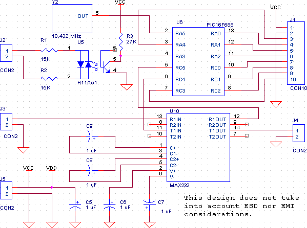
Schematic
This is a generic Renard schematic, not specific to any particular board. It is intended as the starting point for creating a custom design, and many of the elements of this schematic can be modified for individual circumstances.
AC Input (J2)
This connector is used to bring 110VAC into the board for sensing the AC zero-crossing. The resistors R1 and R2 will need to be changed for operation at other voltages.
High voltage is present on this connector, and great care should taken with this connector and the related components to prevent damage or injury. Do not build this circuit if you are not knowledgeable about working with power-line voltages.
Power Connector (J5)
This is used to provide power (+5V) to the Renard controller.
Serial (RS232) Connectors (J3 and J4)
These connectors are used for input data (J3, from either the PC or an upstream Renard controller) and transmitting data to downstream controllers (J4).
SSR Connector (J1)
This connector is designed to interface with the Simpleio TRIAC8 board. The current firmware versions assume that the SSRs are configured in a current-sink mode. The outputs of the PIC are active low. In the inactive state the outputs are high, and are driven low to activate the SSR. The normal firmware will cause the outputs to driven low for about 30 μS (for 60 Hz operation, slightly longer for 50 Hz operation). This fairly narrow pulse will be latched in both the opto-coupler and the triac in the SSR, extending the cycle until the AC voltage drops back to 0.
In many cases it may be desireable to replace J1 with connectors that are better suited to the particular application.
RS232 Voltage Converter (U10, C8 and C9)
This is the classic MAX232 circuit used for converting between RS232 voltage levels (+/- 15V) and TTL logic levels (0 to 5V). This circuit may be replaced with RS485 interface chips (such as the SN75176 or SN75179) if operation with RS485 is desired.
Firmware
To be added.
