Renard 24HC: Difference between revisions
No edit summary |
|||
| Line 37: | Line 37: | ||
:::*The part numbers printed on the PCB are outdated and many have been replaced. The schematic will be updated to match the BOM in the near future. | :::*The part numbers printed on the PCB are outdated and many have been replaced. The schematic will be updated to match the BOM in the near future. | ||
:::*There is a 6 pin socket provided in the kit for the H1AA11 but if used, it creates an interference with the transformer. It can be assembled this way but removal of the H1AA11 will not be possible. | :::*There is a 6 pin socket provided in the kit for the H1AA11 but if used, it creates an interference with the transformer. It can be assembled this way but removal of the H1AA11 will not be possible. | ||
:*Install Resistors R1 -> R24. These are 180 Ohm 1/4 Watt Resistors for 120VAC Operation. | |||
:*Install Resistors R25 -> R53. These are 680 Ohm 1/4 Watt Resistors. R49 -> R53 are for the Diagnostic LEDs near the center of the PCB. | |||
:*Install four 1kOhm Resistors. Two will be located above the transformer block and the other two are located below the RJ45 Jacks. | |||
:*Install three 27kOhm Resistors. Two are located below the RJ45 Jacks and one just above the transformer | |||
:*Install 120 Ohm Resistor below the RJ45 Jack | |||
:*Install the 1N5239 Diode just below the RS485 chips | |||
:*Install the 1N5229 Diode just below the RS485 chips. This may be substituted with a 1N5239 in some kits. | |||
:*Install the 1N4001 Diode. This is located just above the transformer. | |||
:*Install 24 Six Pin sockets. These are for the MOC3023 chips. Note the direction of the notch on the socket and ensure it matches the PCB. If you are planning on soldering the MOC3023 chips directly to the board, then skip this step. | |||
:*Install one (1) Six Pin socket for the H1AA11. Note the direction of the notch on the socket and ensure it matches the PCB. If you are planning on soldering the H1AA11 chips directly to the board, then skip this step. | |||
:*Install one (1) Six Pin socket for the Diode Bridge. Note the direction of the notch on the socket and ensure it matches the PCB. If you are planning on soldering the H1AA11 chips directly to the board, then skip this step. You will need to remove two of the pins from the socket to get this to fit. Simply push up on the two middle pins and pull them out from the top. | |||
:*Install two (2) Eight Pin Sockets. Note the direction of the notch on the socket and ensure it matches the PCB. These are for the RS485 chips | |||
:*Install three (3) Fourteen Pin Sockets for the Microprocessors. Note the direction of the notch on the socket and ensure it matches the PCB. | |||
:*Install the oscillator. Note that one corner of the case is pointed...ensure this matches the silkscreen on the PCB. | |||
:*Install five (5) 0.1 uF Capacitors. These are not polarized. If the leads do not match the holes, use a pair of needle nosed pliers to bend the leads to match. Do not pull or bend the lead right up to the body of the capacitor. | |||
:*Install the five (5) indicator LEDs. The color of the LEDs may vary. The shorter leg of each LED goes into the SQUARE pad...WITH ONE EXCEPTION. The COMM FR pads are backwards and this LED must be installed with the LONG LEAD in the square pad. | |||
:*Install the fuse clips. The clips may need to be bent back slightly to fit properly. | |||
:*Install the Jumper Headers. These are four (4) sets of three pin headers. Alternatively, you can use a small jumper wire for the Transformer On/Off and the 120/240VAC selector. | |||
:*Install channel output terminals. These are listed in the BOM as a single six pin terminal. However, these can be substituted with 2pin or 3 pin units that can be assembled together to create a six terminal block. Assemble these prior to installing by sliding them together (there is a small key/keyway on the side) | |||
:*Install two (2) 10uF Electrolytic Capacitors. Note the STRIPE along the body of the capacitor. This is the NEGATIVE lead. | |||
:*Install the four (4) angled terminals. Assemble these prior to installing by sliding them together (there is a small key/keyway on the side) | |||
:*Install two (2) RJ45 Jacks along the top of the PCB | |||
:*Install the voltage regulator. Note that the flat part of the regulator will face the RJ45 jacks at the top of the PCB. | |||
:*Install twenty four (24) TRIACs. These are the chips that actually switch the AC current on and off. One trick to installing these is to attach them to the heat sink first, then install an entire side at one time. | |||
:*Install the 1000 uF Electrolytic Capacitors. Note the STRIPE along the body of the capacitor. This is the NEGATIVE lead. | |||
:*Install the Three Pin and Two Pin Power terminals. Assemble these prior to installing by sliding them together (there is a small key/keyway on the side) | |||
:*Install the Heat Sink on the Voltage Regulator. This will take a bit of heat to get installed as the entire Heat Sink will need to heat up a bit. | |||
:*Install the H1AA1 and the Diode Bridge if you have not already done so. | |||
:*Install the Transformer. Note the location of Pin 1 of the transformer. There are numbers on the PCB and the Transformer itself. | |||
== Testing Points== | == Testing Points== | ||
Revision as of 14:46, 19 February 2013
Renard 24HC
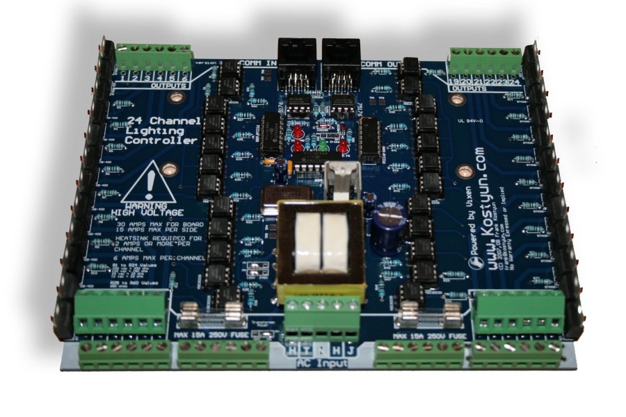
- The Renard 24HC Dimmer is the lastest edition of Frank Kostyun's 24 Channel All-In-One Christmas Lights Controller.
WLC Ventures now stocks the Renard 24HC here.
Disclaimers
- The standard disclaimers pertaining to the information contained on this wiki page are listed here.
Schematic
Previous comments about the schematic being identical to the Renard 64 is not correct.
RavingLunatic created the schematic below by tracing out the board. Note that this is NOT an official schematic, may have errors, and some reference designators are were derived for this schematic. This schematic is old and is being revised.
Media:Renard24 V33 Schematic package.pdf
Layout
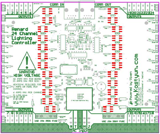
Renard 24HC PCB
Assembly Instructions
For a full step by step document on how to build the Renard 24, please click the following link:
Renard 24 Assembly Instructions - original
There have been changes made to both the board and the Bill of Materials that are inconsistent with the above document. The document is dated but is still a good resource for assembling the HC. Please note the following issues:
- The instructions call for two different Zener Diodes to be installed. Some kits are being supplied with two 1N5239B instead.
- The current kit from WLC Ventures may use different numbers and types of terminals. For instance, where the BOM calls for 3 x 2 position terminals, the kit may contain 2 x 3 position terminals.
- The part numbers printed on the PCB are outdated and many have been replaced. The schematic will be updated to match the BOM in the near future.
- There is a 6 pin socket provided in the kit for the H1AA11 but if used, it creates an interference with the transformer. It can be assembled this way but removal of the H1AA11 will not be possible.
- Install Resistors R1 -> R24. These are 180 Ohm 1/4 Watt Resistors for 120VAC Operation.
- Install Resistors R25 -> R53. These are 680 Ohm 1/4 Watt Resistors. R49 -> R53 are for the Diagnostic LEDs near the center of the PCB.
- Install four 1kOhm Resistors. Two will be located above the transformer block and the other two are located below the RJ45 Jacks.
- Install three 27kOhm Resistors. Two are located below the RJ45 Jacks and one just above the transformer
- Install 120 Ohm Resistor below the RJ45 Jack
- Install the 1N5239 Diode just below the RS485 chips
- Install the 1N5229 Diode just below the RS485 chips. This may be substituted with a 1N5239 in some kits.
- Install the 1N4001 Diode. This is located just above the transformer.
- Install 24 Six Pin sockets. These are for the MOC3023 chips. Note the direction of the notch on the socket and ensure it matches the PCB. If you are planning on soldering the MOC3023 chips directly to the board, then skip this step.
- Install one (1) Six Pin socket for the H1AA11. Note the direction of the notch on the socket and ensure it matches the PCB. If you are planning on soldering the H1AA11 chips directly to the board, then skip this step.
- Install one (1) Six Pin socket for the Diode Bridge. Note the direction of the notch on the socket and ensure it matches the PCB. If you are planning on soldering the H1AA11 chips directly to the board, then skip this step. You will need to remove two of the pins from the socket to get this to fit. Simply push up on the two middle pins and pull them out from the top.
- Install two (2) Eight Pin Sockets. Note the direction of the notch on the socket and ensure it matches the PCB. These are for the RS485 chips
- Install three (3) Fourteen Pin Sockets for the Microprocessors. Note the direction of the notch on the socket and ensure it matches the PCB.
- Install the oscillator. Note that one corner of the case is pointed...ensure this matches the silkscreen on the PCB.
- Install five (5) 0.1 uF Capacitors. These are not polarized. If the leads do not match the holes, use a pair of needle nosed pliers to bend the leads to match. Do not pull or bend the lead right up to the body of the capacitor.
- Install the five (5) indicator LEDs. The color of the LEDs may vary. The shorter leg of each LED goes into the SQUARE pad...WITH ONE EXCEPTION. The COMM FR pads are backwards and this LED must be installed with the LONG LEAD in the square pad.
- Install the fuse clips. The clips may need to be bent back slightly to fit properly.
- Install the Jumper Headers. These are four (4) sets of three pin headers. Alternatively, you can use a small jumper wire for the Transformer On/Off and the 120/240VAC selector.
- Install channel output terminals. These are listed in the BOM as a single six pin terminal. However, these can be substituted with 2pin or 3 pin units that can be assembled together to create a six terminal block. Assemble these prior to installing by sliding them together (there is a small key/keyway on the side)
- Install two (2) 10uF Electrolytic Capacitors. Note the STRIPE along the body of the capacitor. This is the NEGATIVE lead.
- Install the four (4) angled terminals. Assemble these prior to installing by sliding them together (there is a small key/keyway on the side)
- Install two (2) RJ45 Jacks along the top of the PCB
- Install the voltage regulator. Note that the flat part of the regulator will face the RJ45 jacks at the top of the PCB.
- Install twenty four (24) TRIACs. These are the chips that actually switch the AC current on and off. One trick to installing these is to attach them to the heat sink first, then install an entire side at one time.
- Install the 1000 uF Electrolytic Capacitors. Note the STRIPE along the body of the capacitor. This is the NEGATIVE lead.
- Install the Three Pin and Two Pin Power terminals. Assemble these prior to installing by sliding them together (there is a small key/keyway on the side)
- Install the Heat Sink on the Voltage Regulator. This will take a bit of heat to get installed as the entire Heat Sink will need to heat up a bit.
- Install the H1AA1 and the Diode Bridge if you have not already done so.
- Install the Transformer. Note the location of Pin 1 of the transformer. There are numbers on the PCB and the Transformer itself.
Testing Points
The HC has 7 test points (TP1 to TP7)
TP1: GND
TP2: +5VDC
TP3: +12v
TP4: 12vac
TP5: 12vac
TP6: RS485A / RJ45 Pin 5
TP7: RS485B / RJ45 Pin 4
Design Notes for the HC PCB
The COMM FR LED pads are backwards - the cathode (short leg on the LED) will go into the round hole
Renard 24HC Jumper Settings and Options
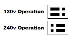
120/240v Jumpers: Allow for setting the transformers input voltage (labeled as JP1 and JP2.)
Zero Cross: If on, the board will insert the zero cross signal on the RJ45 pin 3 (labeled as JP3.) This is used to send a ZC signal to another board such as a Ren64 or Ren16.
![]()
Transformer On/Off: If on, the transformer recieves power from the left power input.
![]()
12v Jumpers: Located below the transformer, these can be installed to use the board in 12vac only mode (for use with MR16 LED lamps, also labeled as JP5 and JP6.)
Firmware
All Renard Firmware is located here: Renard_Firmware
BOM
    Part           Qty          Description
Renard 24HC PCB     1       Renard 24 Channel PCB
571-7969494         1       See note below for v3.3
595-SN75176BP       2       RS-485 Interface ICs Bus Diff
511-L7805CV         1       LM7805 Voltage Regulator
821-DB102G          1       Subsitute part 512-DF01M
532-7136DG          1       Heat Sink for 5V regulator
271-27K-RC          3       27k ohm 1/4 watt resistor
271-1K-RC           4       1k ohm 1/4 watt resistor
271-120-RC          1       120ohm 1/4 watt resistor
625-1N4001-E3       1       Standard Rectifiers Vr/50V Io/1A
78-1N5239B          2       Zener Diodes 9.1 Volt 0.5 Watt
838-3FD-320         1       Larger Transformer use part 838-3FD-420
782-H11AA1          1       Optocouplers Bi-Directional Input
520-TCF1843-X       1       Full Size Crystal Clock Oscillators DIP-14 5V 18.432MHz
140-HTRL25V1000-RC  1       Hi-Temp Radial Electrolytic Capacitors 25V 1000uF 105C
140-HTRL25V10-RC    1       Hi-Temp Radial Electrolytic Capacitors 25V 10uF 105C
534-3517            4       Fuse Clips and Holders PC FUSE CLIP 5 MM
504-GMA-15          2       5mm x 20mm Fast Acting Fuses 125VAC 15A Fast Acting
511-BTA04-700TRG   24       Triac Driver (24 needed) soon to be replaced by 511-BTA06-600
859-MOC3023        24       MOC 3023 Optocoupler
579-PIC16F688-I/P   3       Microchip PIC 16F1688'''
604-WP63ID          4       Red T1 3/4 LED, or any 10-30ma LED
604-WP1503GD        1       Green T1 3/4 LED or any 10-30ma LED
271-180-RC         24       180ohm 1/4 watt resistor
271-680-RC         29       680ohm 1/4 watt resistor
581-SA105E104MAR    5       .10 uF Ceramic Capacitor
571-9-146281-0      1       .100 three pin header(4 needed) Part specified is a 40 pin, cut off size that is needed.
571-2-382811-1      4       .100 Shunt (4 needed) You may also "steal" these off of old computer parts.
571-1-390261-2      2       8 pin DIP socket
571-1-390261-3      3       14 pin DIP socket
571-1-390261-1     26       Optional 6 Pin Socket for Optocoupler & H11AA1
571-5556416-1       2       RJ45 Sockets (2 needed) orientation doesn't matter. Specified part is same as the Ren64
571-2828376         6       6 Position Screw Down Terminal (Ren24 2.5 needs 4 of these)
158-P02EK508A3-E    4       3 Position Angled Screw Down Terminal
158-P02EHK508V3-E   1       3 Position Screw Down Terminal (power input) - higher current rating than prior part
158-P02EHK508V2-E   1       2 Position Screw Down Terminal (power input) - higher current rating than prior part
Hooking Up the Renard 24HC
Data Connections
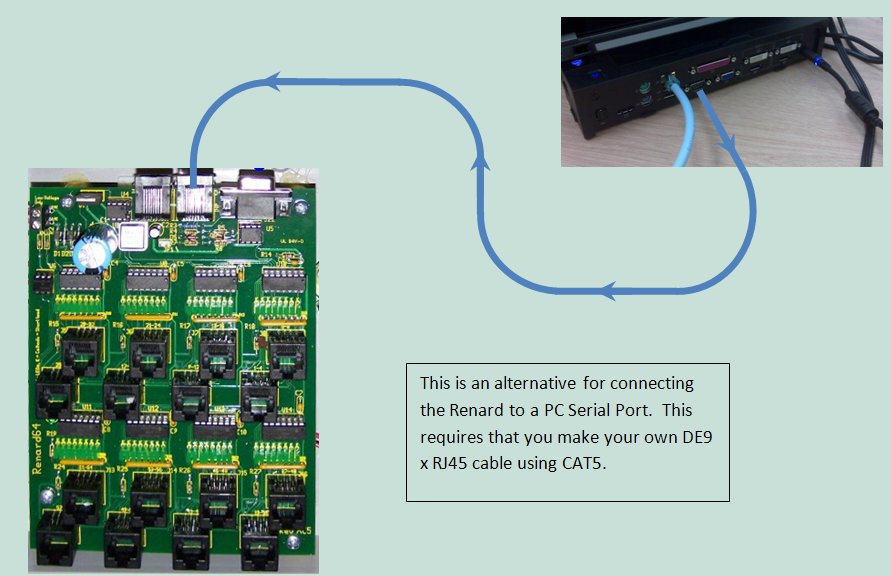
Data Cables
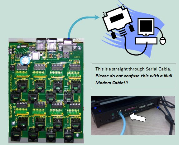
- Data cables for Renard board connection directly to computer COMM port
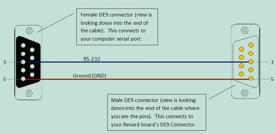
 PC DE9 Pin 3 to Renard 64XC JDP1 Pin 3
 PC DE9 Pin 5 to Renard 64XC JDP1 Pin 5
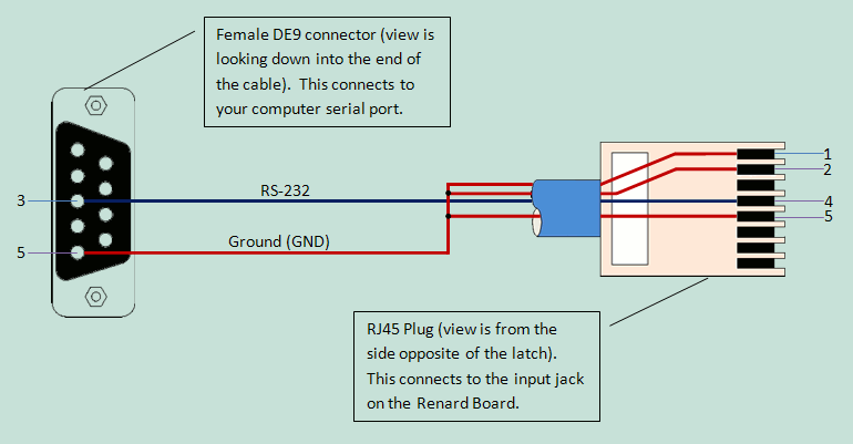
 PC DE9 Pin 3 to RJ45-pin 4
 PC DE9 Pin 5 to RJ45-pin 5 and pin 1 and/or pin 2
- Data cable for Renard board connection using a RS232->RS485 converter or DMX Adapter
- Due to the many different types of RS232->RS485 converters available the drawing only refers to the signals coming from the converter. Check the documentation for your converter to figure out how/where to hook up the correct wires.
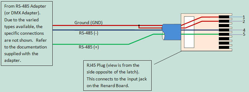
 RS485 Adapter Pinouts
    RS485(-) Signal to RJ45-pin 4
    RS485(+) Signal to RJ45-pin 5

 DMX via XLR Connectors - Pinouts
    XLR connector pin 1 (GND) to RJ45-pin 1 and/or pin 2
    XLR connector pin 2 (Data-) to RJ45-pin 4
    XLR connector pin 3 (Data+) to RJ45-pin 5

 DMX via RJ45 Connectors - Pinouts
    RJ45 connector pin 1 (Data+) to RJ45-pin 5
    RJ45 connector pin 2 (Data-) to RJ45-pin 4
    RJ45 connector pins 7 & 8 (GND) to RJ45-pins 1 & 2
- Data cable for Renard board connection to other Renard boards - Daisy Chain
- Generally only a regular straight-thru CAT5 cable is required to connect any Renard controller to another Renard controller. For the few exceptions (ie Ren24 V2.5), check the wiki page for those boards to see what their unique requirements are.
Cable Lengths
- Data cables connecting Renard boards directly to a computer COMM port should not be longer than 50 feet according to the RS-232 standard. This distance can also be greatly reduced by using poor quality cables. However, this distance can be increased buy using high quality, low impedance cables.
- Data cables connecting Renard boards directly to other Renard boards or any other RS-485 source can be up to 4,000 feet in length for data rates up to 100Kbps according to the RS-485 standard.
Connecting Multiple Renard Boards
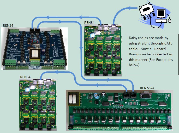
- The above image shows how Renard boards in general can be daisy chained together. Renard 64XC board is connected to the PC Serial Port. This board this then connected to a REN24HC, a REN SS24 and another REN64. The boards that are used in the image are just an example of how all Renard boards can be connected together. (The XMUS Ren16 and the REN24 v2.5 do have some issues...so read up on them first)
- Key things to remember when connecting ALL Renard boards together:
- You only need one instance of the Renard Dimmer plug-in in Vixen for each physical COMM port being used. You just need to make sure that the plug-in is setup for the total number of channels for all the Renard boards connected to that COMM port. In the above example, the plug-in would be set for 176 channels.
- The total number of Renard boards that can be connected together depends on the event period and the baud rate being used. More information on the total number of channels capable with Renard systems can be found here.
Computer Setup
- VIXEN Settings
- The Renard 64 board requires the Renard Dimmer [Vixen 1.1.*] or Renard Dimmer (modified) [Vixen 2.*] Plug-In.
- Renard Dimmer Plug-In Settings:
- Protocol Version: 1
- COM1 (or whichever COM port you are connected to)
- Baud: 57600 (default firmware value, if firmware is changed then this needs to be changed to match the firmware)
- Parity: None
- Data bits: 8
- Stop bits: One
- Hold port open during the duration of the sequence execution: Checked
- Renard Dimmer Plug-In Settings:
Errata for Rev HC PCB
1) COMM FR LED pads are backwards
