Renard 24HC
Renard 24HC
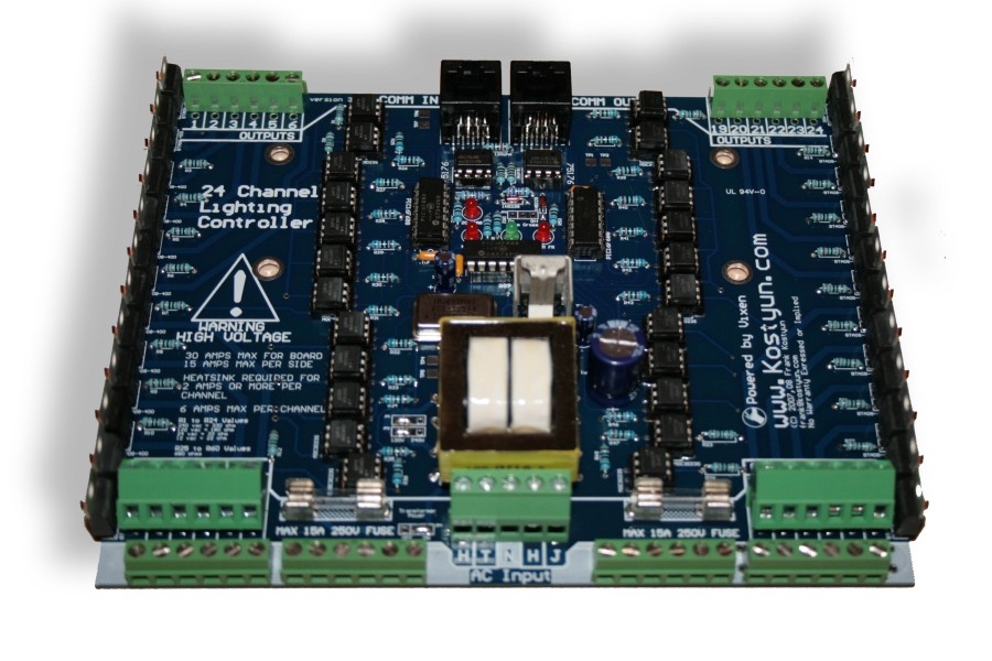
- The Renard 24HC Dimmer is the lastest edition of Frank Kostyun's 24 Channel All-In-One Christmas Lights Controller.
WLC Ventures now stocks the Renard 24HC here.
Disclaimers
- The standard disclaimers pertaining to the information contained on this wiki page are listed here.
Schematic
Previous comments about the schematic being identical to the Renard 64 is not correct.
RavingLunatic created the schematic below by tracing out the board. Note that this is NOT an official schematic, may have errors, and some reference designators are were derived for this schematic. This schematic is old and is being revised.
Media:Renard24 V33 Schematic package.pdf
Layout
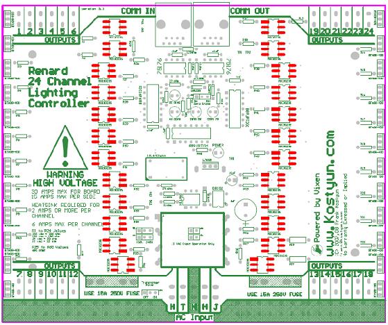
Renard 24HC PCB
Assembly Instructions
For a full step by step document on how to build the Renard 24, please click the following link:
Renard 24 Assembly Instructions - original
Testing Points
The HC has 7 test points (TP1 to TP7)
TP1: GND
TP2: +5VDC
TP3: +12v
TP4: 12vac
TP5: 12vac
TP6: RS485A / RJ45 Pin 5
TP7: RS485B / RJ45 Pin 4
Design Notes for the HC PCB
The COMM FR LED pads are backwards - the cathode (short leg on the LED) will go into the round hole
Renard 24HC Jumper Settings and Options
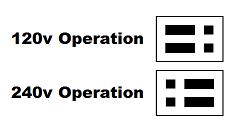
120/240v Jumpers: Allow for setting the transformers input voltage (labeled as JP1 and JP2.)
Zero Cross: If on, the board will insert the zero cross signal on the RJ45 pin 3 (labeled as JP3.) This is used to send a ZC signal to another board such as a Ren64 or Ren16.
![]()
Transformer On/Off: If on, the transformer recieves power from the left power input.
![]()
12v Jumpers: Located below the transformer, these can be installed to use the board in 12vac only mode (for use with MR16 LED lamps, also labeled as JP5 and JP6.)
Firmware
All Renard Firmware is located here: Renard_Firmware
BOM
Renard 24HC PCB  1        Renard 24 Channel PCB
571-7969494 1             '''See note below for v3.3'''
595-SN75176BP 2           '''RS-485 Interface ICs Bus Diff'''
511-L7805CV 1             '''LM7805 Voltage Regulator'''
821-DB102G 1              '''subsitute part 512-DF01M'''
532-7136DG 1              '''Heat Sink for 5V regulator'''
271-27K-RC 3              '''27k ohm 1/4 watt resistor'''
271-1K-RC 4               '''1k ohm 1/4 watt resistor'''
271-120-RC 1              '''120ohm 1/4 watt resistor'''
625-1N4001-E3 1           '''Standard Rectifiers Vr/50V Io/1A'''
78-1N5239B 2              '''Zener Diodes 9.1 Volt 0.5 Watt'''
838-3FD-320 1             '''Larger Transformer use part 838-3FD-420'''
782-H11AA1 1              '''Optocouplers Bi-Directional Input'''
520-TCF1843-X 1           '''Full Size Crystal Clock Oscillators DIP-14 5V 18.432MHz'''
140-HTRL25V1000-RC 1      '''Hi-Temp Radial Electrolytic Capacitors 25V 1000uF 105C'''
140-HTRL25V10-RC 1        '''Hi-Temp Radial Electrolytic Capacitors 25V 10uF 105C'''
534-3517 4                '''Fuse Clips and Holders PC FUSE CLIP 5 MM'''
504-GMA-15 2              '''5mm x 20mm Fast Acting Fuses 125VAC 15A Fast Acting'''
511-BTA04-700TRG 24       '''Triac Driver (24 needed) soon to be replaced by 511-BTA06-600'''
859-MOC3023 24            '''MOC 3023 Optocoupler'''
579-PIC16F688-I/P 3       '''Microchip PIC 16F1688'''
604-WP63ID 4              '''Red T1 3/4 LED, or any 10-30ma LED'''
604-WP1503GD 1            '''Green T1 3/4 LED or any 10-30ma LED'''
271-180-RC 24             '''180ohm 1/4 watt resistor'''
271-680-RC 29             '''680ohm 1/4 watt resistor'''
581-SA105E104MAR 5        '''.10 uF Ceramic Capacitor'''
571-9-146281-0 1          '''.100 three pin header(4 needed) Part specified is a 40 pin, cut off size that is needed.'''
571-2-382811-1 4          '''.100 Shunt (4 needed) You may also "steal" these off of old computer parts.'''
571-1-390261-2 2          '''8 pin DIP socket'''
571-1-390261-3 3          '''14 pin DIP socket'''
571-1-390261-1 26         '''Optional 6 Pin Socket for Optocoupler & H11AA1'''
571-5556416-1 2           '''RJ45 Sockets (2 needed) orientation doesn't matter. Specified part is same as the Ren64'''
571-2828376 6             '''6 Position Screw Down Terminal (Ren24 2.5 needs 4 of these)'''
158-P02EK508A3-E 4        '''3 Position Angled Screw Down Terminal'''
158-P02EHK508V3-E 1       '''3 Position Screw Down Terminal (power input) - higher current rating than prior part'''
158-P02EHK508V2-E 1       '''2 Position Screw Down Terminal (power input) - higher current rating than prior part'''
PC to Renard Cable
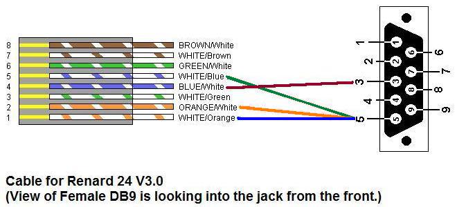
The Renard 24 board has on-board power supply circuitry and on-board zero-crossing circuitry, so all that it needs on the RJ45 cable are data signals and ground. If you are using RS232 input and connecting it directly to the PC serial port, the following cable pin outs will work:
PC DB9 Pin 3 to RJ45-pin 4
PC DB9 Pin 5 to RJ45-pins 1,2,5 (pins 1 and 5 are required, pin 2 is optional).
If you are using a RS-232 to RS-485 converter, the pinout is Pin 5 to A+ and Pin 4 to B-. This is the same as for the Ren 16.
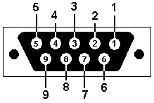 Female DB9 connector as if you were looking into the end of it from the outside.
sink.
Errata for Rev HC PCB
1) COMM FR LED pads are backwards
