Renard 24LV
Revision 1.0 Board (2008 Co-Op #1)
Schematic
Media:Renard64_sch_001.pdf (please note, the schematic is identical to the Renard64)
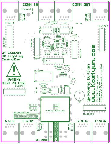
Layout
COOP PCB V1.0
Co-Op Board 3.0 Assembly Instructions
Currently in-process!
Design Notes for v 3.0 Co-Op Board
BOM
PCB
1  Ren24v3                             Renard 24-Port PCB

Board Specific Parts:
571-7969494 1
595-SN75176BP 2
511-L7805CV 1
821-DB102G 1                           '''SUB PART 512-DF01M'''
532-7136DG 1
271-27K-RC 3
271-1K-RC 4
271-120-RC 1
625-1N4001-E3 1
78-1N5239B 2
838-3FD-320 1
782-H11AA1 1
520-TCF1843-X 1
140-HTRL25V1000-RC 1
140-HTRL25V10-RC 1
534-3517 4
504-GMA-15 2


Parts from the Common Parts List: (Common parts are the parts that are not unique to the Ren24, and may also be used in other designs)
579-PIC16F688-I/P 3
604-WP63ID 4
604-WP1503GD 1
271-180-RC 24
271-680-RC 5
581-SA105E104MAR 5
571-41032390 1
571-3828115 4
571-1-390261-2 2
571-1-390261-3 3
571-3902611  2  (Optional 6 Pin Socket for Optocoupler & H11A1 - Recommended)
571-5564161 6

Common Parts Description:
ST Microelectronics BTA08 Triac Driver (24 needed)
Microchip PIC 16F1688 (3 needed)
Red T1 3/4 LED (4 needed)
Green T1 3/4 LED (1 needed)
680ohm 1/4 watt resistor (5 needed)
.1 uF Ceramic Capacitor (5 needed)
.100 three pin header (7 needed) Part specified is a 40 pin, cut off size that is needed.  Note - 1 header will give you enough to do 3 boards.
.100 Shunt (7 needed) You may also "steal" these off of old computer parts.
6 pin DIP socket (optional - 25 needed)
8 pin DIP socket (2 needed)
14 pin DIP socket (3 needed)
RJ45 Sockets (6 needed) orientation doesn't matter. Specified part is same as the Ren64
The + pin of the DB102 is on the bottom right both of the ~ should be on the left.
The jumpers on the board are for 120/240v operation. If you don't plan on using the boards on 120v these can be hard soldered with a jumper wire.
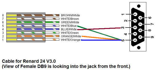
PC to Renard24 LV Cable
PC DB9 Pin 3 to RJ45-pin 4
PC DB9 Pin 5 to RJ45-pins 1,2,5 (pins 1 and 5 are required, pin 2 is optional).
If you are using a RS-232 to RS-485 converter, the pinout is Pin 5 to A+ and Pin 4 to B-. This is the same as for the Ren 16.
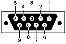
 Female DB9 connector as if you were looking into the end of it from the outside.

