|
|
|
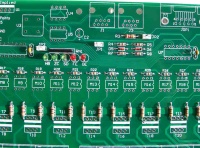
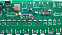
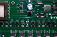
- Start by checking the PCB over for any obvious production faults. Check for traces that end abruptly or have cracks/breaks in them. Also check that all holes are clear. Also, look for damage that may have occured during shipping and handling. Large scratches over traces can be an issue.
|
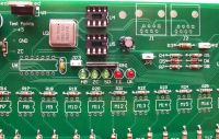
- Install two 750 ohm resistors R1 & R2. Make sure that the resistors have a value of 750 ohms [violet/green/brown/gold stripes]. These resistors have no polarity to worry about.
|
- Install the 120 ohm resistor R3. Make sure that the resistor has a value of 120 ohms (brown/red/brown/gold stripes). This resistor have no polarity to worry about.
|
- Install two (2) 1K ohm resistors R4 and R7. Make sure that the resistors have a value of 1K ohm [brown/black/red/gold stripes].
|
- Install three (3) 27K ohm resistors R5, R8, and R14. Make sure that the resistors have a value of 27K ohms [red/violet/orange/gold stripes].
|
- Install one (1) 300 ohm resistors R19. Make sure that the resistors have a value of 330 ohms [???/???/???/gold].
|
- Install four diodes D1 thru D4. The diodes will have a silver/grey stripe on a black body. Make sure that this stripe lines up with the stripe on the PCB silk screen.
|
- Install zener diode D5. The diode must be installed correctly. The diode should have a black stripe on the orange/red body. Make sure that this stripe lines up with the stripe on the PCB silkscreen.
|
- Install zener diode D6. The diode must be installed correctly. The diode should have a black stripe on the orange/red body. Make sure that this stripe lines up with the stripe on the PCB silkscreen.
|
- Install eight (8) 0.1uF capacitors C3-C10. These capacitors are not polarized so the orientation is not critical.
|
INSTALLATION NOTE:
The following resistor network is a "bussed" type resistor network. This means that the seven (7) resistor components (pins 2-8) are all connected in a common buss to pin 1. Installing the resistor network backwards will cause a multitude of malfunctions. So please take the time to make sure they are installed correctly.
|
- Install the eight (8) 330 ohm resistor networks R10-R13 and R20-R23. The resistor network should have a dot on it to indicate pin 1. Insert pin 1 of the resistor network into the square solder pad.
|
- Install the Power LED, D7. The LEDs are polarized and must be installed with the proper orientation. The short lead is the cathode and must be placed in the square solder pad.
|
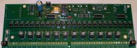
- Install sixty four (64) Green Channel LEDs. The LEDs are polarized and must be installed correctly. The short lead is the cathode and must be placed in the square solder pad. This is marked on the silkscreen with a "K".
|
- Install three 2-pin vertical headers JP1, JP2 & JP3 (PN# 538-22-03-2021). These headers have no polarity to worry about.
|
|
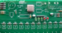
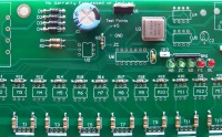
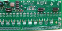
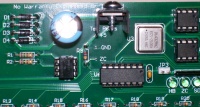
- Install the clock oscillator U3 (PN# 520-TCH1843-X). The oscillator must be installed in the correct orientation. The oscillator has three rounded corners and one squared corner, make sure that the squared corner is positioned to match the PCB silkscreen (upper left corner).
|
|
- Install the voltage regulator U1 (PN# 511-LF50CV). The voltage regulator must be installed correctly. The voltage regulators tab/heat sink must be aligned with wider line of the PCB silkscreen outline (facing towards the PCB top edge).
|
|
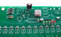
- Install the 2200uF capacitor C1 (PN# 140-XRL16V2200-RC). This capacitor is polarized and must be installed correctly. The capacitor should have a black stripe on the body to indicate which lead is negative. The positive lead of the capacitor will be the longer lead. Make sure that the positive lead is placed in the square solder pad.
|
|
- Install the 47uF capacitor C2 (PN# 667-ECA-1CM470). This capacitor is polarized and must be installed correctly. The capacitor should have a silver/grey stripe on the body to indicate which lead is negative. The positive lead of the capacitor will be the longer lead. Make sure that the positive lead is placed in the square solder pad.
|
|
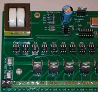
- Install four fuse clips (PN# 534-3517) Note: they are directional for proper fit of the fuse. A helpful installation tip here would be to put a fuse in the clips when you position them in their mounting holes. This will help keep them correctly aligned so that the fuse will fit properly.
|
|
INSTALLATION NOTE:
Pin 1 of the following IC sockets must be aligned with the square solder pad. Another way to verify that you installed them correctly is to make sure that the notch on the socket is aligned with the notch on the PCB silkscreen outline.
|
- Install two 8-pin IC sockets for U4 & U5 (PN# 571-1-390261-2).
|
|
- Install three 14-pin IC sockets for U6, U7 & U8 (PN# 571-1-390261-3).
|
|
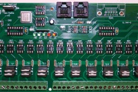
- Install 25 6-pin IC sockets for U2, M1 thru M24 (PN# 571-1-390261-1).
|
|
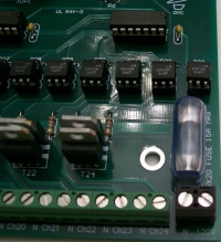
- Install 24 triacs T1 thru T24 (PN# 511-BTA04-700T). The triacs must be installed correctly. The triac tab/heat sink must be aligned with wider line of the PCB silkscreen outline. The tab/heat sink of the odd numbered triacs will facing the even numbered triacs and vice versa.
|
|
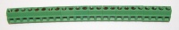
- Install 24 terminal blocks for Ch1 thru Ch24 (PN# 571-2828372). These terminal blocks have a small interlocking tab that allows the terminals to be "stacked" together to create a larger terminal block. It is easier to go ahead and "stack" twelve terminal blocks together first and then mount them on the PCB.
|
|
- Install two terminal blocks for 120V input (PN# 571-7969492).
|
|
- Install the transformer TF1 (PN# 838-3FS-312).
|
|
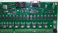
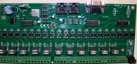
- Install two RJ45 modular jacks J1 & J2 (PN# 571-5556416-1). Due to minor variations in manufacturing, some RJ45 jacks are a tighter fit than others. Care should be taken to ensure that the pins are aligned first before applying too much pressure to seat the locking lugs through the board.
|
|
- Install the DE9 connector JDP1 (PN# 152-3409).
|
|
If you are unsure about your ability to build this board, then you should go to The Beginner's Setup Guide at this point. The Beginner's Setup Guide will walk you thru some initial tests to make sure that everything is working correctly before inserting the IC chips.
|
INSTALLATION NOTE:
Pin 1 of each IC must be aligned with pin 1 of the corresponding socket. This can be verified by noting that the notch on the IC is aligned with the notch on the socket.
|
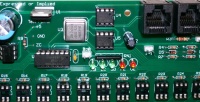
- Install the H11AA1 optocoupler U2 (PN# 782-H11AA1).
|
|
- Install three PIC microcontrollers U6, U7 & U8 (PN# 579-PIC16F688-I/P). The PICs need to be programmed with the appropriate firmware before installation. More info on programming PICs can be found here.
|
|
- Install two RS232/RS485 Interface ICs U4 & U5 (PN# 511-ST485BN).
|
|
- Install 24 optoisolators M1 thru M24 (PN# 859-MOC3023).
|
|
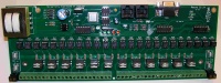
- Install the heat sink (PN# 532-577102B00) on voltage regulator U1. The mounting hardware and heat transfer compound are not included in the BOM since any common hardware can be used to attach the heat sink. If you don't have any heat transfer compound handy, you can use PN# 532-249. In the picture the heat sink is attached using a #8 x 3/8" metal screw found at home depot.
|
|
- Install two fuses (PN# 504-GMA-10) and two fuse covers (PN# 534-3527C).
|
|


