Renard Start Address Configuration Guide
Background
- One of the main goals of the original Renard controller design was simplicity, and it was the original intent that all Renard controllers were identical, 8-channel units. Simplicity allowed for a person to expand a system simply by building and plugging in another 8-channel controller; 8 would then become 16, 16 would become 24, etc. Because the controllers were identical they were also interchangeable – it didn’t matter which was the first one and which the second or third one. There was no need for the user to set an address for this controller or that controller; it was simply “plug in and go.” However, with the advent of 16, 24, and even 64-channel Renard controllers, the concept has expanded over the years and has evolved into increasingly complex networks of controllers and thousands of feet or even miles of wires. But the original firmware that has been used in the Renard system has remained simple and unaddressable. Until now.
What is the Start Address?
- The start address is a new feature of Renard firmware that makes a single Renard controller addressable. Not in the purest sense such as an IP address or network name, but in a relative sense to the channel information that is sent to it. The feature allows a Renard controller to start decoding channels at a specific channel out of an entire range of channels. For example, instead of a controller automatically displaying channels 1-24, it can be set to skip channels 1-24 and start with channel 25 instead.
- The feature is primarily designed to aid those who use wireless communications in their light displays (although it can also be used with wired RS-485 systems). With wireless, it’s easy to broadcast all channels; all receivers in range of the transmitter will then pick up the same signal simultaneously. The start address provides a way for a wireless controller to begin decoding data at a specific channel out of the entire broadcast set of channels.
- IMPORTANT: The information provided here was intended to be used with the popular PIC16F688 chip that most Renard controllers use. While the general concepts apply to all Renard-type firmware, the actual start address and its relationship to the actual channel may be different for chips other than the PIC16F688. For example, note that for the PIC16F1825 chip (which was implemented later) the start address begins at 1 for channel 1 whereas the start address for the 16F688 began at 0 for channel 1. To convert the information below to apply to the PIC16F1825 chip, simply increment the stated start address by one.
Who should use it?
- The Renard start address feature is considered to be an advanced concept and is very likely to be quite confusing to someone new to DIY lighting controls. To successfully implement the feature, a solid understanding of how Renard controllers function normally is extremely important. One must also know how to modify assembly language program code, how to compile the code into HEX format and flash a PIC with the updated firmware. It’s good to remember that if you make a mistake with the start address, you can always restore your Renard controller to normal operation by reflashing the PIC with the original Renard firmware.
Renard Start Address Concepts
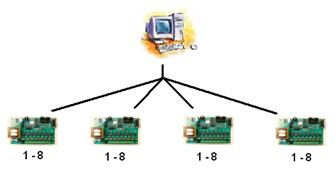
- For the sake of explanation, consider a typical 32-channel Renard system utilizing a computer and four identical 8-channel controllers where the computer’s control signal connects to the first controller and all the other controllers are in a daisy-chain configuration, such as the example below.
- Our example uses an 8-channel controller because it has only a single PIC16F688 chip, which will be critical to understanding how to set the starting address feature later on. Another helpful concept is to remember that many Renard controllers can be connected to a single serial port and that there’s a limit to the total number of channels a single port can handle, and this is generally based on the sequence timing you use in Vixen. This is important because the starting address pertains to all the channels that come from a single serial port. If you use both COM1 and COM2, the starting addresses for controllers on COM1 are independent from starting addresses for controllers on COM2.
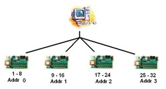
- Let’s change the normal Renard layout by connecting a 4-way splitter to the serial cable and then plugging each of the four 8-channel controllers into the splitter so that all four controllers can receive the same 32-channel signals simultaneously in a sort of “serial broadcast.” In this example, each controller uses the first eight channels of the 32-channel data and passes the remaining channels to the next controller – except the controllers aren’t connected to one another! Therefore, in this layout, each 8-channel controller gets only the first 8 channels and channels 9-32 don’t go anywhere because there is no “daisy chain” of controllers – each is an individual, standalone controller and has nowhere to pass the unused channel information along.
- Now let’s reflash the PIC in each controller with a “start address” that tells the PIC that instead of automatically taking the first channels it gets, to start decoding data at a different channel number instead.
- • Address 0 means normal operation.
- • Address 1 means start with channel 9 (skip channels 1-8)
- • Address 2 means start with channel 17 (skip channels 1-16)
- • Address 3 means start with channel 25 (skip channels 1-24)
- Now all 32 channels are in use again.
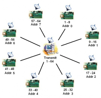
- Let’s switch gears again and replace the 32-channel setup with a 64-channel wireless model where all 64-channels are broadcast wirelessly from the computer and each 8-channel wireless controller is configured using individual starting addresses from the full 64-channel broadcast. Using identical controllers makes it easy to calculate the starting address for each unit. (This particular design would also require that all Ren-W wireless adapters be configured with the same PAN ID and no individual XBee radio addressing would be used at all. This is the purest “global broadcast” mode possible and one of the simplest ways to implement a Ren-W network yet retain individual controller channel assignments.)
- The start address concept is most effective when all channel information can be distributed to all controllers simultaneously and is a perfect fit for those who use Ren-W wireless adapters.
How to calculate the start address
- The formula for the start address is A=(C-1)/8 where C is a channel number that you want the controller to start with. Examples: 9, 17, 25, 33, 41, 49, 57, etc. Do you notice that the channel number is always one more than a number evenly divisible by eight? This is because each PIC in a typical Renard controller controls 8 channels. Therefore, the last channel number in a Renard controller is always a factor of 8 and why the next channel number is 1 greater.
Multi-PIC Controllers
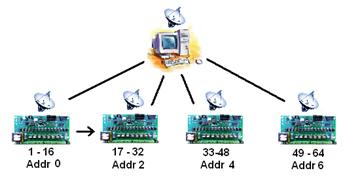
- So far, the examples have used only 8-channel controllers that use a single PIC. When you use controllers that have multiple PICs, the formula works the same way. Let’s examine a 64-channel system using four 16-channel wireless Renards.
- Apply the formula: A=(C-1)/8 for the first controller: 1 – 1 = 0, then 0/8 = 0 so the start address of the first controller is zero.
- We want the 2nd controller to start with channel 17, so applying the A=(C-1)/8 formula, we get a start address 2 for the 2nd controller: 17-1= 16, divide 16/8 = 2.
- We want the 3rd controller to start with channel 33, and applying the formula we get a start address of 4: (33 – 1 = 32, then 32/8 = 4).
- The 4th controller will start with channel 49, and we calculate that start address at 6: (49 – 1 = 48, then 48/8 = 6).
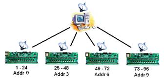
- Here’s an example of a 96-channel wireless design using four, 24-channel controllers. Applying the A=(C-1)/8 formula we arrive at start address 0, 3, 6 and 9 for the four controllers.
Mixing controllers with different channel counts
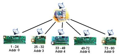
- When start addresses are used with controllers of varying channel counts, just use the formula to calculate the start address for each controller one controller at a time. In this 80-channel design with 5 controllers, in L-R order each controller’s channel counts are 24, 8, 16, 24 and 8. You can do the math yourself.
- It’s obviously a good idea to pre-plan your display and assign controllers to various portions of your display depending on the number of channels you need in each location. As you do that, you’ll find it helpful to label each controller in some way to denote where in the display it will be, the expected channels it will use and its start address. This will make it easier later on when/if something isn’t working right. Without labeling the controller, there will be no outwardly visible way to know what it’s supposed to be doing except by watching its lights.
How to Set the Start Address
- You will need:
- • Renard firmware version 20090915.asm. (You can get it here: Media:Renard-20090915.asm)
- • A text editor such as Windows Notepad.
- • MPASM, or other Microchip-compatible compiler to generate the HEX code for the PICs
- • A PIC programmer for PIC16F688 chips.
- Step-by-step procedure:
- 1. Open the ASM file using the text editor and find the following section of code (it will be one of the earliest sections of the code following the copyright information):
- START_ADDR should normally be 0. It is changed to another value if you
- wish for the particular PIC to ignore a certain number of (8-byte) records
- at the start of a frame (for wireless operation, mostly).
- define START_ADDR 0
- 1. Open the ASM file using the text editor and find the following section of code (it will be one of the earliest sections of the code following the copyright information):
- 2. Change the number at the end of the define START_ADDR line. The number you enter must be an integer.
- 3. Save the file.
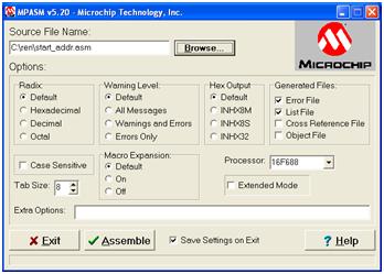
- 4. Open MPASM, be sure it is configured for the 16F688 chip, use the BROWSE button to find the Source File Name of your ASM file (the example here is start_addr.asm)
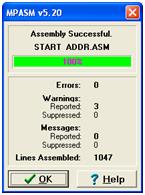
- 5. Click the Assemble button. You may encounter warning messages such as in the example below, and these are expected. But if there are no errors you should be fine. Click the OK button to complete the operation.
- 6. Open the PIC programmer and flash the designated PIC with the resulting HEX file you just assembled. Remember, this should be the FIRST PIC in a controller that has more than one PIC chip.
- 7. Insert the PIC back in your controller. Be sure to label the controller so that you know the start address and the expected channels it will use.
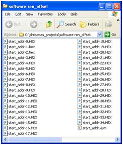
- Time Saver Suggestion: if you know that you will have many controllers with special start addresses but you don’t yet know what they are, after you compile the first ASM into HEX code, rename the resulting HEX file afterward with something that denotes what the starting address of that file is and simply repeat the process, changing the value, saving the file, recompiling into HEX, etc. and create multiple HEX files, such as in the example to the right. You may not use all of them, but they’ll always be available for you to quickly reflash a PIC whenever necessary. In this example, startaddr-34.HEX equates to 34 x 8 = 272 channels, virtually at the top of the recommended maximum for a single serial port using 57,600bps and sequencing at 50ms intervals.
Common Questions & Answers
- Which PIC gets the start address?
- Only the first PIC in each controller. If you don’t know which PIC that is or it isn’t marked, follow the circuit board tracings from the channel 1 output back to its PIC.
- Can I set the address in more than one PIC on a controller?
- Technically yes, but in practice, don’t do it. It may make it very difficult for you to analyze what’s going on in your display afterward. Set the start address only on the first PIC and leave the others alone.
- Do I need to do anything special in Vixen?
- No, just sequence like you normally do. It may be helpful to create a special sort order for the Vixen profile so that channels can be viewed together by controller instead of by color or location in the display. The idea is to have some method for cross-referencing various channels to various controllers for troubleshooting purposes. An alternative method would be to create a testing sequence that activates all channels on a single controller for a few seconds, then move to another controller, etc. In any event, you'll probably want some method to test the layout to make sure the controllers have the right addresses and you see what you expect to see.
- What if I need to replace a controller in my display?
- Use another Renard controller of the same channel count that has the first PIC flashed with the same START_ADDR and simply plug it in.
- Can I flash the PIC in my Renard controller in-circuit?
- Unless you have added in-circuit programming capability to your controller or have built a special cable/connector that can clamp onto the PIC's pins, you will have to remove the first PIC and flash it with your PIC Programmer as you normally would. The concept of adding an in-circuit header to a Renard controller is a good one – perhaps someone will come up with a DIY solution in the future!
- If I move a controller in my display, should I change the start address, too?
- Maybe. It depends on what channels you want the controller to use.
- Can I change my XBee modules’ PAN ID addresses, too?
- Yes, and in some cases it may actually be required. For example, if you have two serial ports and plan to broadcast channel controls out on both, you will need to use two PAN IDs, one for each port. If you used the same PAN ID for both ports, the XBee receivers will get very confused when they get transmissions from two sources simultaneously! Remember, only XBee radios that use the same PAN ID can communicate with one another. If you experience interference even when using different PAN IDs, you can also change the XBee channel setting to use a different channel.
- Does the Ren-C have start address capability?
- No. The start address pertains only to the firmware for the 16F688 chip; the Ren-C uses different firmware for its 16F627A chip. However, if you think outside the box a little, you can certainly have a start address on the controller immediately before the Ren-C and daisy chain the Ren-C off of that controller. For example, you might set the start address for an SS8 controller to 6 so that the SS8 begins at channel 49, connect the Ren-C/595 to the SS8’s RS-OUT jack and the Ren-C/595 would then become channels 57-120. (Of course, remember that the Ren-C still requires a ZC signal as well.)
- Does the start address work with DMX?
- No, DMX has its own addressing scheme.
- How do I disable the start address?
- Either reflash the chip with a version that has the START_ADDR set to zero or reflash using the original 16F688 firmware that doesn’t include the start address option.
- Does the start address work with the Renard diagnostic firmware?
- No. The diagnostic firmware does not have the start address capability.
- How do I test the controller to determine if I used the right start address?
- If your controller has diagnostic LEDs, remember that they react to channels 2, 5-6-7-8. For example, if the controller’s start address is set to 6, channel 1 on that controller is actually Vixen channel 49. Therefore, channels 2, 5-6-7-8 are using Vixen channels 50, 53-54-55-56 and you should be able to use the Vixen channel test function to turn on the diagnostic LEDs one at a time. (We’re assuming that all channels are on the same serial port for this example.)
- I use several serial ports on my PC. How do I know what address to use?
- This is where it gets confusing and you literally have to map it out on paper. Let’s say that you have two COM ports, and each port carries 128 channels for a total of 256 channels on your Vixen screen. Luckily, Vixen only allows defining a contiguous group of channels to a specific plugin and the plugin is assigned to its own port, so it shouldn’t be too difficult to identify which Vixen channels go to which port. Let’s assume in this example that Vixen channels 1-128 are assigned to COM1 and channels 129-256 are assigned to COM2. A Renard controller doesn’t know which port its channels are coming from; it only knows that channel information is coming to it. Therefore, the start address is relative to the total number of channels on that port. So in this example with 128 channels on COM1 and another 128 on COM2, a controller that has a start address of 2 would start with Vixen channel 17 if it were being controlled via COM1 but would start with Vixen channel 145 (128 + 17) if it were being controlled via COM2.
- The bottom line with using multiple serial ports is that you need to know which controllers are being controlled from each port, and assign the controllers their own order relative to that port. So while you may have sixteen, 16-channel Renard controllers in your display, it may help your organization to think of them as 1A, 2A, 3A etc. and 1B, 2B, 3B, etc. where eight are assigned to port A and the other eight assigned to port B.
- In any event, this takes some careful thought, a pencil and a pad of paper to carefully map out which controllers are where in your display, which port is being used to control them, how many channels each has and what the start_addr will be. It’s certainly not difficult math, but it does require some clear thinking.
- Is it possible to overlap channels by use of the start address?
- Yes, but you run the risk of orphaning channels later on. Let’s say that you had 72 channels in use on three, 24-channel controllers and you decided to change and use the 3rd controller to double-up on channels 41-48 to handle some extra lights and the resulting extra electrical current required.
- Controller #1: channels 1-24, start address = 0 (calculation: 1 – 1 = 0, then 0/8 = 0)
- Controller #2: channels 25-48, start address = 3 (calculation: 25 – 1 = 24, then 24/8 = 3)
- Controller #3: channels 41-64, start address = 5 (calculation: 41 – 1 = 40, then 40/8 = 5)
- Suddenly channels 65-72 don’t come on because by overlapping 8 channels, you’ve effectively reduced the total channel coverage from 72 down to 64. The point is that overlapping can cause some unexpected results, but it is certainly possible. You just have to plan for it.
- Can any channel be the start address?
- No, because the PICs in Renard controllers are 8-bit chips and therefore, the firmware requires that the address is based on 8-channel boundaries. However, you can simulate other start addresses by configuring the address so that the controller covers the desired channel(s) you want but then don’t plug any lights into the controller for channels you don’t want. For example, an address of 2 starts with channel 17, but if you really only want lights on channels 21-24, only plug lights into channels 21-24 and leave the others empty. This wastes a little capacity, of course, but nobody ever said that you always have to plug lights into every channel on a controller – you may decide to use only some channels while leaving others without lights plugged into them. It has the same end effect.
- Can I use the start address with my wired controllers?
- Yes, and if you chain other controllers off of the specially addressed one, they will behave normally just like you’d expect them to. Also remember that it’s possible to skip channels completely, too. For example, if you have two 24 channel controllers and you want one of them to use start address 0 (for channels 1-24) and the other controller at start address 6 (for channels 49-72) channels 25-48 won’t be anywhere in the display. Channels that are “skipped” like this just disappear unless you configure other controllers to display them.
- Can I use the start address with daisy-chained controllers?
- Yes, but you should only set the start address on the FIRST controller and leave the remaining daisy chained controllers set to start address zero or use standard Renard firmware on them. Example: think about three SS16 controllers daisy chained together. Essentially, the three controllers form one large 48-channel controller, or at least that's what it looks like in a Vixen sequence. If you have a 120-channel sequence and you set the start address of the first of the SS16 controllers to be 4, you're essentially telling the first one to skip 32 channels and start with channel 33. Therefore, the three daisy chained SS16s would then use channels 33-80 because the start address of the first one establishes the starting channel address and the data flows through the other two controllers just like normal.
- Can I set the start address on EACH controller that's still daisy chained together?
- Yes, but this practice is not recommended. Determining which channels a controller will react to becomes quite confusing and even more difficult to troubleshoot and plan in your sequences. The bottom line is that while it will work, it will make it very confusing to use. To figure it out, you need a complete understanding of how the Renard firmware works and how the data packets are reformatted during the daisy chain process from one PIC to the next. However, in practice, doing so makes it possible for to make two or three controllers react to an extremely wide range of channels which you may not otherwise be able to do.
- Do I have to change the addresses every year?
- Maybe. If your display changes every year, then probably yes. If you put up exactly the same display every year and put exactly the same controllers out in the same locations, then perhaps not.
- If I run into trouble, who can I call for help?
- Because the Renard start address concept is quite dependent on the physical layout of your display as well as the physical connections between units and the configuration of Vixen on your computer, the one who can best deal with problem issues is YOU because you can actually SEE these pieces of your display. Take it one step at a time, get one controller working at a time, and you’ll work through them. However, dirknerkle authored this document, so try him first. That said, if your question is about setting the start address for multiple pics on the same controller or setting different start addresses for daisychained controllers, you're on your own.
Table of Start Address Settings
- Here's a table of START_ADDR settings and the respective starting channel for that controller.
- ADDR --- Channel
- 0 ------ 1
- 1 ------ 9
- 2 ------ 17
- 3 ------ 25
- 4 ------ 33
- 5 ------ 41
- 6 ------ 49
- 7 ------ 57
- 8 ------ 65
- 9 ------ 73
- 10 ------ 81
- 11 ------ 89
- 12 ------ 97
- 13 ------ 105
- 14 ------ 113
- 15 ------ 121
- 16 ------ 129
- 17 ------ 137
- 18 ------ 145
- 19 ------ 153
- 20 ------ 161
- 21 ------ 169
- 22 ------ 177
- 23 ------ 185
- 24 ------ 193
- 25 ------ 201
- 26 ------ 209
- 27 ------ 217
- 28 ------ 225
- 29 ------ 233
- 30 ------ 241
- 31 ------ 249
- 32 ------ 257
- 33 ------ 265
- 34 ------ 273
- 35 ------ 281
- 36 ------ 289
- 37 ------ 297
- 38 ------ 305
- 39 ------ 313
- 40 ------ 321
- 41 ------ 329
- 42 ------ 337
- 43 ------ 345
- 44 ------ 353
- 45 ------ 361
- 46 ------ 369
- 47 ------ 377
- 48 ------ 385
- 49 ------ 393
- 50 ------ 401
- ADDR --- Channel

