SSRez: Difference between revisions
| Line 16: | Line 16: | ||
The SSRez can be used as is for most all of the designs found here on DIYC. Some specific uses may require the Bill of Materials to be modified. If the information is not 100% clear, please ask! | The SSRez can be used as is for most all of the designs found here on DIYC. Some specific uses may require the Bill of Materials to be modified. If the information is not 100% clear, please ask! | ||
==SSRez Features== | |||
<ul> | |||
<li>Designed to fit in the TA-200 Enclosure</li> | |||
<li>Made with 2oz Copper boards for 7A total capacity</li> | |||
<li>Trace spacing supports 240VAC use</li> | |||
<li>RJ45 Jack layout for Top or Side Load for flexibility</li> | |||
<li>On board 5V Logic Power LED</li> | |||
<li>Triac layout designed with Heat Sinks in mind</li> | |||
<li>Separate Terminals for each wire making the connections easier</li> | |||
<li>Wiring "channel" makes the connections easier</li> | |||
<li>Clean and Distinct Low Voltage/High Voltage Isolation</li> | |||
<li>Fuse Position and layout allows for the Optional Fuse Cover</li> | |||
</ul> | |||
== Disclaimers == | == Disclaimers == | ||
Revision as of 13:31, 6 July 2011

Why Another SSR?
There are lots of SSR designs out there. However, Sean's SSRoz is one of the best. It is compact and functions great and without this initial work, the SSRez may not exist! However, a shortcoming of the design was that it was not designed with a specific enclosure in mind. The initial move towards the SSRez involved changing the layout to fit the TA-200 Telephone Demarc Enclosure from YourBroadbandStore.com.
In order to keep the board to a minimum size and the board cost down, the SSRoz has all the neutral connections off board. So, take all the neutrals and connect them with a large wire nut (five 16AWG neutrals!) Once connected, where does the massive chuck of wire go? :) This led to adding terminals for the neutrals...now this is not inexpensive. The cost was offset in part by removing the vertical fuse holder and replacing it with inexpensive fuse clips.
Lastly, the RJ45 connector could be difficult to remove with the locking pin as the pin ends up in a tight corner. A vertical RJ45 jack made this so much easier. Now, some users like the right angle connection. The great thing is that both types will fit the board. So, if you want the "Dino Option" feel free to use the right angled connector.
While changing every thing around, the power traces were beefed up a bit to allow a slightly higher power throughput. This allows for a 7A fuse in place of the original SSRoz fuse of 5A.
so....start out trying to change one problem..and end up with a whole new layout!
The SSRez can be used as is for most all of the designs found here on DIYC. Some specific uses may require the Bill of Materials to be modified. If the information is not 100% clear, please ask!
SSRez Features
- Designed to fit in the TA-200 Enclosure
- Made with 2oz Copper boards for 7A total capacity
- Trace spacing supports 240VAC use
- RJ45 Jack layout for Top or Side Load for flexibility
- On board 5V Logic Power LED
- Triac layout designed with Heat Sinks in mind
- Separate Terminals for each wire making the connections easier
- Wiring "channel" makes the connections easier
- Clean and Distinct Low Voltage/High Voltage Isolation
- Fuse Position and layout allows for the Optional Fuse Cover
Disclaimers
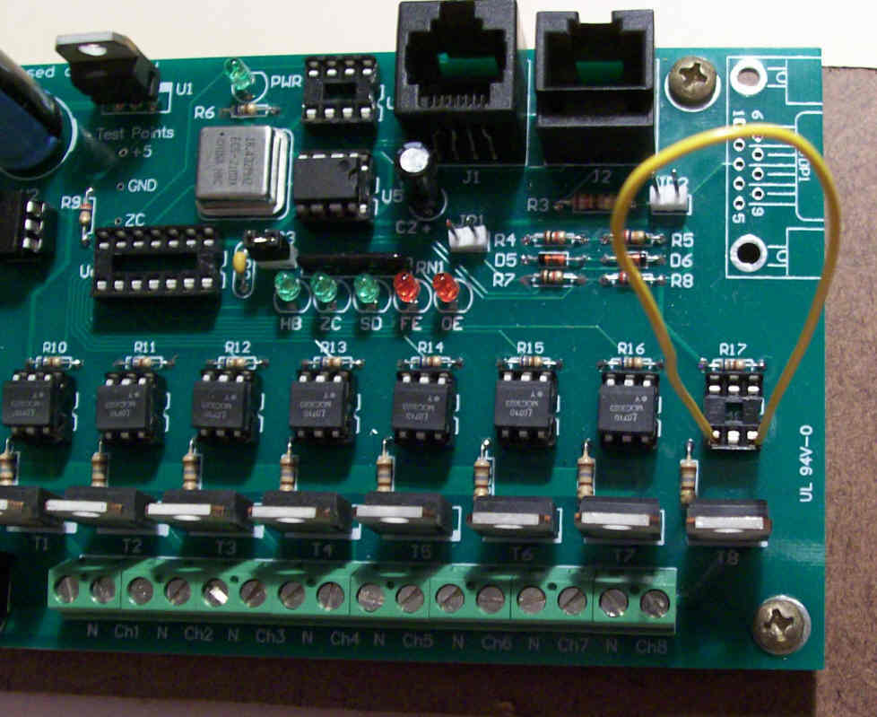
PLEASE NOTE: THE OVERLAY FOR THE TRIACS IS INCORRECT FOR Version 1.3. THE TAB SHOULD FACE THE BOTTOM OF THE BOARD, NOT THE TOP. Rev 1.3a is correct and is now shipping
The standard disclaimers apply to the SSRez and can be found here.
Schematic

The pdf file can be found here
Bill of Materials
QTY    Mouser #:           Description
1      571-5556416-1      Modular Jacks 8 PCB TOP ENTRY marked RJ45
1      504-GMC-7          5mm x 20mm Medium Time Delay Fuses 125VAC 7A Med Time Delay
4      511-BTA04-700T     Triacs 4 Amp 700 Volt marked Q1, Q2, Q3, and Q4
2      534-3517           Fuse Clips and Holders PC FUSE CLIP 5 MM
1      604-WP7104IT       LED Standard HI EFF RED TRANS marked LED
5      660-CF1/4C681J     1/4Watt Axial Leaded Carbon Film Resistors 680ohms 5% marked R5, R6, R7, R8 and R9
4      660-CF1/4C181J     1/4Watt Axial Leaded Carbon Film Resistors 180ohms 5% marked R1, R2, R3 and R4
4      859-MOC3023        Optocomponents Optocoupler TRIAC marked U1, U2, U3 and U4
4      571-1-390261-1     IC Sockets 6P ECONOMY TIN  (Optional!) also marked U1, U2, U3 and U4
5      571-28228372       Terminal Blocks 5.08MM PCB MOUNT 2P
3                         Screw,#8x1/2" Pan Head Sheet Metal
1      TA-200             Enclosure
1                         Male Plug Power Cord, Rated for 8A Minimum
4                         Female Plug Power Cord, Rated for 4A Minimum
Now the above is the base Bill of Materials for 120VAC operation. There are, however, some options that can be handled. These are listed below.
240VAC Operation
Change R1, R2, R3 and R4 to 330 Ohm and replace the fuse with one rated for 240VAC (one listed is for 125VAC). However, a fuse with a rating of 7A at 250VAC is a heck of alot of power. It is perfectly okay to use a fuse with a lower rating if your overall load is small.
36 VAC Operations for those folks Down Under using toroidal transformers...
Change R1, R2, R3 and R4 to 47 Ohm. The fuse rating is still a MAX of 7A. It does not change because the voltage has been reduced.
24 VAC Operations for those folks Down Under using toroidal transformers...
Change R1, R2, R3 and R4 to 33 Ohm. The fuse rating is still a MAX of 7A. It does not change because the voltage has been reduced.
FireGod
If the SSRez is going to be used with a FireGod system, Resistors R5-R8 may need to be changed. If the channel LEDs are used on the field modules AND the interface board voltage regulator is 5VDC, replace R5, R6, R7, R8, and R9 with 510 Ohm Resistors. You must also use the "Sinking Code" in the FireGod Field Modules when using the SSRez.
Construction Information
Oh, many of you will be building more than one SSRez at a time. An assembly line mindset really helps. This means, put all the resistors on all the boards before going to the next part.
Now, get your tools together! Cause here we we go.....
1. Sort your parts in the order of assembly. This sounds odd but really helps especially if you have never done this type of assembly before.

2. Check your resistors...make sure the part matches whats written on the bag. Every once in a while, the supplier will give you the wrong part. It never hurts to grab a mulitmeter and check those resistors values. Hmmmmm...how to read the color bands on the resistors can be found here.
3. Inspect your boards for damage. Basically, you are looking for cut traces, deep scratches and other damages since they were shipped.

4. Install the 5 680 Ohm Resistors marked R5, R6, R7, R8 and R9 [blue, silver, red, gold]. Bend them first to match the holes (I have been known to bend all my resistors while watching TV!) Insert them through the holes and bend the lead back to about 60 deg on both side to hold them in place. Solder each connection and trim off the excess lead with flush cut snips. Note: Some electronics folks will tell you to do this differently. There is a high specification soldering procedure (typically for military items) that says to cut the leads to length, and then solder them in place. This will work but this level of detail is not required for this board.

5. Install the 4 180 Ohm Resistors [brown, silver, red, gold] for 120VAC operation or the 330 ohm resistors [orange, orange, red, gold] for 240VAC operation. These are marked R1, R2, R3 and R4. The installation process is the same as in Step #4.

6. Install the optional 6 pin sockets for U1, U2, U3 and U4. Beware of the orientation of the notch. This is a visual aid to make sure that you put the MOCs in correctly. Match the notch with the notch in the silkscreen. Sometimes, a piece of tape can help here. I usually put all four on, cover them with a board and just flip it over. Solder the six pins on each socket. If you choose not to install the sockets, then install the 4 MOCs here in the same manner.

7. Install the Power LED. Orientation is critical. The short leg (the Cathode or K) of the LED must go into the square pad. The silkscreen has this marked with a K Bend the legs out to a 60 deg angle to hold the LED in place. Then solder the leads and trim the excess.

8. The fuse clips are next. Be aware the orientation of these as well. There is a small ridge inside the clip to keep the fuse from sliding out axially. This ridge must go to the side opposite the fuse. Using a fuse to hold the two clips in place while soldering has been suggested.

9. The 5 terminal blocks are next. The terminals must be assembled first. There is a notch and a pin on the side to mate the 5 parts into on long 10 position terminal. Once assembled, insert the block into the board with the openings for the wires facing outboard. Starting from the middle and working outward, solder in all the pins. These pins are a bit larger and can take more heat and solder than the previous items.

10. Now its time for the the TRIACs. These pins are large and they can be difficult to solder at first. If you have problems...tin the leads prior to inserting them into the boards. Solder the pins in place and trim the excess. NOTE for Ver 1.3!!! : THE SILKSCREEN FOR THE TRIACS IS INCORRECT. THE TAB SHOULD FACE THE BOTTOM OF THE BOARD (THE RJ45 Side), NOT THE TOP. Version 1.3a has the corrected Silkscreen

11. Last, but not least, install the RJ45 Jack. The jack should snap into the 2 large mounting holes and hold itself in place. The pins are very small and solder very fast so be careful not to add too much solder.
12. Clean the board with Isopropyl Alchohol to remove any residual flux.
13. Using good lighting and a magnifier, inspect all the solder joints. Solder bridges, cold joints, too little solder and too much solder are typical errors.
14. Install the 4 MOCs if you did not in Step #6. Watch the orientation by keeping the notch in the same direction as the silk screen.
15. Install the fuse.

16. Mount the SSRez into the enclosure by using 3 each #8x1/2" Pan head zinc coated sheet metal screws. The screw size is defined by the enclosure bosses. The screw may get a touch tight as it makes the final last few mm.

17. Pull the small rubber inserts on the bottom on the enclosure and using a good sharp knife, cut along the lines in the gasket. An Exacto Knife works really well for this. Cut both gaskets all along all the three lines.
18. Now you are ready to wire up the SSRez per the diagram below.
Wiring The SSRez
The following image is how to connect the SSRez to the Power Supply (AC Hot and AC Neutral)and your Lights (Chan #1, Chan #2, Chan #3, Chan #4, Neutral #1, Neutral #2, Neutral #3 and Neutral #4).
Please note that the Neutrals are all bussed. There is no difference between the terminals. The Chan #'s and AC In are specific and must be wired in this order.

Heat Sink
Template Coming Soon
Troubleshooting
'This section is under construction...please do not use for the time being....
Symptom(s):
- Channel remains on constantly
- Channel does not come on when commanded
- Triac gate resistor burnt/blown
Possible Problem(s):
- Bad triac
- Triac in Backwards
- Bad opto
- Opto/MOC in Backwards
- Bad/missed Solder Joints
Troubleshooting Flow

Troubleshooting Steps
- Turn OFF AC power
- Are any of the triac gate resistors (R1-R4) burnt/blown/damaged?
- If so, replace that resistor and check the solder pads on the associated TRIAC. Blown gate resistors are usually caused by a missed solder connection on the TRIAC.
- Remove the PIC from the controller for this channel.
- If not already installed, attach some test lights to the terminal block of the failing channel.
- Connect power to the H and N terminal blocks
- Turn ON AC power
- Test lights should be OFF
- If the test lights are ON, go to step <XX>
- Using the following table, momentarily use a jumper to turn ON the test lights
- Test lights should come ON when the jumper is connected to the locations in the table. Now this table has eight tests as they are the 8 channels from a single PIC Microcontroller. However, the SSRez has only 4 channels. The channels in the chart for 5-8 are for a different SSRez.
Controller
ChannelOptoisolator Test Lights
at SSRezConnect Jumper Wires between 1 U1 Channel 1 2 U2 Channel 2 3 U3 Channel 3 4 U4 Channel 4 5 U1 Channel 1 6 U2 Channel 2 7 U3 Channel 3 8 U4 Channel 4
- Does the previously bad channel now work? If it does:
- Turn OFF AC power
- Install PIC back into the controller
- Begin testing again where previous failure was noted
- Turn OFF AC power
- Replace the opto (U1-U4) controlling the bad channel
- Return to step 8 and repeat tests with the new opto
- Continue here if replacing the opto did not fix the problem
- Turn OFF AC power
- Remove the opto (U1-U4) controlling the bad channel
- Turn ON AC power
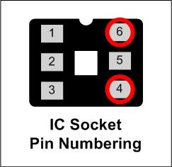
SAFETY NOTICE:
In the following step you will be using a jumper wire (small piece of insulated wire) to jump
120 VAC from one pin to another. You need to be very sure that you know what pins you
are putting the jumper to before you proceed. Applying 120 VAC to the wrong
location could/can cause some very undesirable results..
- Momentarily use a jumper wire and connect between pins 4 and 6 of the opto socket
- If the lights still do not come on, it should only be one of the following things:
- Bad triac
- Bad/open triac gate resistor
- Bad solder joints on the triac, opto socket, triac gate resistor or the terminal block
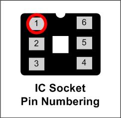
- If the lights did come on, measure the voltage at the opto socket pin 1
- It should be 5 VDC
- If incorrect, check the current limiting resistor (R5-R8) associated with that opto. You should be able to read approx 5 VDC on both sides of the resistor.
- If correct, then something must have been overlooked during the troubleshooting process. Turn OFF the AC power and reinstall any removed components, then restart the troubleshooting process.
- It should be 5 VDC
- Turn OFF AC power
- Remove the opto (U1-U4) controlling the bad channel
- Turn ON AC power
- Is the test light still ON?
- If the light is still ON then it could be either a bad triac or possibly a bridged solder joint on the triac, opto socket, triac gate resistor or the terminal block.
- If the light is OFF, then replace the opto with a new one and retest
Early Prototype Picture
I have left this image, only to record that the version 1.3 and prototype boards have the silkscreen overlay for the TRIACs reversed.
