Simple Renard RGB+W: Difference between revisions
No edit summary |
|||
| Line 62: | Line 62: | ||
===Housing=== | ===Housing=== | ||
The Simple Renard RGB+W was designed to fit in the [http://www.aflglobal.com/cmspages/bluekey/getfile.aspx?aliaspath=/productlist/Product-Lines/Optical-Connectivity---Apparatus/CableGuard-500-Coax-Demarcation-Enclosure/doc/CG-500-Coax-Demarcation-Enclosure CG-500 Demarcation Enclosure] available from numerous vendors including [http://wlcventures.com/zencart/index.php?main_page=index&cPath=1| www.wlcventures.com]<br/> | |||
=Building the Simple Renard RGB+W= | =Building the Simple Renard RGB+W= | ||
Revision as of 03:34, 1 April 2012
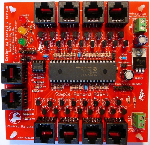
Simple Renard RGB+W 32 Channel DC Controller
THIS WIKI IS A WORK IN PROGRESS AND IS CURRENTLY UNDER CONSTRUCTION.
Please see the standard Disclaimers
What is the Simple Renard RGB+W?
TBD
How does the Simple Renard RGB+W work?
TBD
Revision History
The Version v.1b is currently the most recent version of the Simple Renard RGB+W in production.
Simple Renard RGB+W Parts
In addition to the PCB, you will need the following components:
Mouser
| Part | Description | Mouser PN | Qty |
| P1 | Fixed Terminal Blocks 5.08MM VERTICAL 2P wire protector | 571-7969492 | 2 |
| C1,C2 | Aluminum Electrolytic Capacitors - Leaded 35volts 47uF 5x11 20% 2LS | 647-UVZ1V470MDD | 2 |
| C6 | Multilayer Ceramic Capacitors (MLCC) - Leaded 0.33uF 50volts X7R 10% | 81-RDER71H334K1K103B | 1 |
| C3,C4,C5 | Multilayer Ceramic Capacitors (MLCC) - Leaded 0.1uF 50volts Y5V +80-20% 2.5mm L/S | 81-RPEF51104Z2S2A03A | 3 |
| D1 | Zener Diodes 4.3 Volt 0.5 Watt) | 78-1N5229B | 1 |
| D2 | Zener Diodes 9.1 Volt 0.5 Watt) | 78-1N5239B | 1 |
| IC1 | RS-485 Interface IC LP Diff Pairs | 595-SN65LBC179P | 1 |
| IC3 | Linear Regulators - Standard 1A Pos Vol Reg | 512-LM7805CT | 1 |
| IC & Component Sockets 40P DUAL WIPE DIPSKT | 517-4840-6000-CP | 1 | |
| IC5 | Microcontrollers (MCU) 32KB 1536 RAM 36I/O | 579-PIC18F4520-I/P | 1 |
| ICSP | Headers & Wire Housings FLAT HEADER 6P Straight Post tinr | 571-6404526 | 1 |
| JP2 XBee header | Headers & Wire Housings FLAT HEADER 5P Straight Post tin | 571-640452-5 | 1 |
| Shunt for XBheader and Vreg bypass | Headers & Wire Housings Mini Shunt .177" height | 737-MSC-G | 3 |
| JP3 Vreg bypass | Headers & Wire Housings FLAT HEADER 2P Straight Post tin | 571-6404522 | 1 |
| J1-J10 | Ethernet & Telecom Connectors 8 PCB LO PRO R/A | 571-5555164-1 | 10 |
| Status Led | Standard LED - Through Hole YELLOW DIFFUSED | 604-WP132XYD | 1 |
| Power Led | Standard LED - Through Hole RED DIFFUSED | 604-WP132XID | 1 |
| RX/TX Led | Standard LED - Through Hole GREEN DIFFUSED | 604-WP132XGD | 1 |
| R1,R2,R6 | Carbon Film Resistors - Through Hole 1.0Kohms 0.05 | 299-1k-RC | 3 |
| R3,R7 | Carbon Film Resistors - Through Hole 330ohms 5% | 299-330-RC | 2 |
| R4 | Carbon Film Resistors - Through Hole 10Kohms 5% | 299-10k-RC | 1 |
| R5 | Carbon Film Resistors - Through Hole 120ohms 0.05 | 299-120-RC | 1 |
| R9,R10 | Carbon Film Resistors - Through Hole 27Kohms 5% | 299-27k-RC | 2 |
| R11-42 | Carbon Film Resistors - Through Hole 820ohms 5% | 299-820-RC | 32 |
| T1-32 | Transistors Bipolar (BJT) 600mA 75V NPN | 863-PN2222AG | 32 |
| PIC Bypass | Headers & Wire Housings NARROW FLT HDR 3P Straight Post | 571-3-644456-3 | 1 |
| IC & Component Sockets 8P DUAL WIPE DIPSKT | 517-4808-3004-CP | 1 |
Click Here for Mouser Direct Project BOM
Housing
The Simple Renard RGB+W was designed to fit in the CG-500 Demarcation Enclosure available from numerous vendors including www.wlcventures.com
Building the Simple Renard RGB+W
Assembly
The Simple Renard RGB+W is a simple device to assemble and test. It is easiest if you build the units by inserting the various components from smallest to tallest .
- Begin by inspecting the PCBs to look for any defects such as cracks or breaks. The holes on the board should be open on both sides. Then inspect and sort out the various parts for the board.
- Install the resistors:
- Install the capacitors:
- Install the IC socket:
- Install the transistors:
- Install the light emitting diodes:
- Install the 5v linear regulator
- Inspect the board to look for any missing solder joints, solder bridges or cold solder joints.
Congratulations! That completes the construction of the Simple Renard RGB+W !
Final Testing
TBD
Mounting in Housing
TBD
Jumper Settings / Headers
JP1 PIC Option
Currently unused. Normal position is no jumper.
JP2 XBee Header
Pin Layout
1 +5VDC
2 N/C
3 GND
4 RX from 485 chip
5 RX in to PIC
If you are not using a XBee Wireless module place a jumper across pins 4/5.
JP3- Vreg Bypass
Only install jumper on JP3 if you have omitted C1 and IC3 if V+ is +5VDC and well regulated!
JP4 PIC Bypass
Normal position is jumper across pins 2/3.
ICSP
Use for programing PIC on the circuit board.
Power Requirements
TBD
Connecting up the Simple Renard RGB+W
Data
The Simple Renard RGB+W should be connected to a PC and can be driven by the standard Renard Plugin in Vixen.
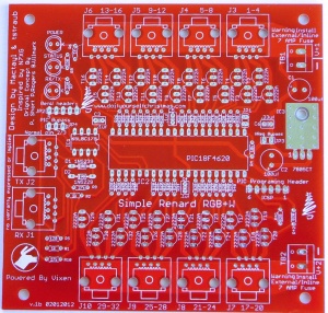
J1 is the data input to the Simple Renard RGB+W
J2 is the data output from the Simple Renard RGB+W
Outputs
J3 is Output channels 1-4
J4 is Output channels 5-8
J5 is Output channels 9-12
J6 is Output channels 13-16
J7 is Output channels 17-20
J8 is Output channels 21-24
J9 is Output channels 25-28
J10 is Output channels 29-32
RJ45 output jacks are wired as follows:
Pin 1 - V+
Pin 2 - Channel 1 Output
Pin 3 - V+
Pin 4 - Channel 2 Output
Pin 5 - V+
Pin 6 - Channel 3 Output
Pin 7 - V+
Pin 8 - Channel 4 Output
The outputs are switched to Ground by the transistors controlled by the PIC.
Power
TB1 (V+1) supplies power to Outputs 1-16 and also supplies power to the Voltage regulator to power the on board circuits.
TB2 (V+2) supplies power to Outputs 17-32.
Firmware
TBD
Schematic
PCB
PCBs are available from N7XG (Dean)
Design Options
TBD
Other Information
TBD
Simple Renard RGB+W Discussion Threads
FAQ
TBD

