Choosing a Pixel Voltage: 5V vs 12V
Intro
There are many Different Styles of Pixels that are available with different design features like shape, integrated circuit and voltage available. Choosing the right pixel depends on your specific use plans and one of the most common questions is which voltage pixel should you buy. Choosing between the two most common voltages, 5vdc and 12vdc depends on how you plan to control and how you layout your pixel setup. There are a few general rules:
- Long strings (>50 pixels) are less likely to need power injection if they are driven by 12vdc.
- Long distances from the controller to the first pixel is easier with 12vdc.
- 12vdc power supplies are more expensive per Amp then 5vdc power supplies.
- Some low cost and homemade controllers only work with 5vdc.
- Some 12vdc pixels use less current then traditional 5vdc pixels.
- Voltage drop and power injection are important issues for both voltages.
- 5VDC pixels are more power efficient then 12VDC pixels.
- 5VDC pixels use less power than 12VDC pixels.
Disclaimers
The standard disclaimers pertaining to the information contained on this wiki page are listed here.
THIS PAGE IS STILL IN DEVELOPMENT AND SUBJECT TO CHANGE. PLEASE COME BACK SOON!
THIS WIKI PAGE IS NOT COMPLETE YET.
How RGB LEDs work
Light Emitting Diodes (LEDs) emit a colored light when the proper voltage is applied across their terminals. A typical Common Anode RGB LED used in pixel strings actually has three LEDs (Red, Green and Blue) inside of one housing.
The specific voltage required to light the LED generally depends on the color of the LED. The following table shows the characteristic voltages ( also called Forward Voltage VF) required for each of the three LEDs inside of the typical RGB LED used in pixels.
| Typical 8mm RGB LED Properties | |||
| Color | Forward Voltage VF @ 20ma | ||
| Minimum | Typical | Maximum | |
|---|---|---|---|
| Red | 1.8V | 2.0V | 2.2V |
| Green | 3.0V | 3.2V | 3.4V |
| Blue | 3.0V | 3.1V | 3.4V |
Since we tend to use commonly available 5VDC or 12VDC power supplies to drive the pixels, we have to drop the voltage and limit the current flowing thru the LEDs using current limiting resistors chosen for each color LED to deliver the proper voltage and current.
Current Limiting Resistors
By using a formula called Ohm's Law you can calculate the size and value resistor you need to drop the supply voltage down from the 5VDC or 12VDC to the VF and current that you need for a specific LED. An example of that calculation is:
- What resistor would you use with a 5VDC power supply and a Blue 8mm LED with a VF of 3.1V?
First you need to calculate the voltage that the resistor needs to drop. That is equal to
VDrop=VPowerSupply - VF=5-3.1=1.9V
The table above recommends a current I of 20 ma for a 8mm LED. The formula for resistance gives us:
R=V/I=1.9/0.02=95Ω Generally you choose a resistor for that value or the next higher standard resistor value , in this case 100Ω.
To calculate the wattage resistor needed you use the formula for Power:
P=VI=(1.9)(0.02)= 0.038W. You would use the next standard size up resistor, 1/8 W.
Power Efficiency of Pixels
Because the power supply voltage is not exactly equal to the VF that the LED needs, there is some power wasted as heat in the current limiting resistor. Many common pixels are designed to use 20ma (0.02A) of current per LED color, or a total of 60ma (0.06A) total per pixel. You can then use Ohm's Law to calculate the power used by the LED and the resistor. From the table below, you can see that a typical 5VDC pixel consumes 0.3W of power and the LED uses 55% of the power and the rest is wasted as heat in the resistor. A typical 12VDC pixel that uses 20ma consumes 0.72W of power and the LED only uses 23% of the power and the rest is wasted as heat. To the human eye there is only a small difference in brightness in the LED by lowering the current thru it, so some 12VDC pixels actually run at only 10ma per LED (compared to the usual 20ma) to lower the overall power consumption to 0.36W, basically cutting the power consumption in half by reducing the brightness of the pixel somewhat.
| Single RGB LED Pixel Power Efficiency | ||||
| 5VDC RGB Pixel @20ma per color | ||||
| Red | Green | Blue | Total | |
|---|---|---|---|---|
| LED Power (W) | 0.04 | 0.064 | 0.062 | 0.166W |
| Resistor Power(W) | 0.06 | 0.036 | 0.038 | 0.134W |
| Total Power (W) | 0.1 | 0.1 | 0.1 | 0.3W |
| 12VDC RGB Pixel @20ma per color | ||||
| Red | Green | Blue | Total | |
| LED Power (W) | 0.04 | 0.064 | 0.062 | 0.166W |
| Resistor Power(W) | 0.2 | 0.176 | 0.178 | 0.72W |
| Total Power (W) | 0.24 | 0.24 | 0.24 | 0.72W |
| 12VDC RGB Pixel @10ma per color | ||||
| Red | Green | Blue | Total | |
| LED Power (W) | 0.02 | 0.032 | 0.031 | 0.083W |
| Resistor Power(W) | 0.1 | 0.088 | 0.089 | 0.277W |
| Total Power (W) | 0.12 | 0.12 | 0.12 | 0.36W |
Instead of wasting all of the power in heating the resistor, some pixel strips actually use 3 LED wired in series for each channel as a more power efficient way to use 12VDC. By doing that the pixel still draws 0.72W per pixel, but the LED power efficiency goes up to 69% compared to 23% when they used only a Single LED! As mntioned above, by cutting the current in half, they can further reduce the power consumed by the pixel in half and therefore some 12VDC pixel strips are actually run at 10ma and only consume 0.36W per pixel of power and are very efficient.
| 3 LED RGB LED Pixel Power Efficiency | ||||
| 12VDC RGB Pixel @20ma per color | ||||
| Red | Green | Blue | Total | |
|---|---|---|---|---|
| LED Power (W) | 0.12 | 0.192 | 0.186 | 0.498W |
| Resistor Power(W) | 0.12 | 0.048 | 0.054 | 0.222W |
| Total Power (W) | 0.24 | 0.24 | 0.24 | 0.72W |
| 12VDC RGB Pixel @10ma per color | ||||
| Red | Green | Blue | Total | |
| LED Power (W) | 0.06 | 0.096 | 0.093 | 0.249W |
| Resistor Power(W) | 0.06 | 0.024 | 0.027 | 0.111W |
| Total Power (W) | 0.12 | 0.12 | 0.12 | 0.36W |
So as seen by the above analysis, there are many factors involved in deciding not only whether to go with 5VDC or 12VDC, but how they are wired as well and what current per pixel they use.
Different Voltage Configurations
A common pixel type uses the WS 2811 integrated circuit to control the RGB LED. This integrated circuit can run on either 5VDC or 12VDC using the appropriate internal and external dropping resistors. As discussed above, there are three common ways they are wired up.
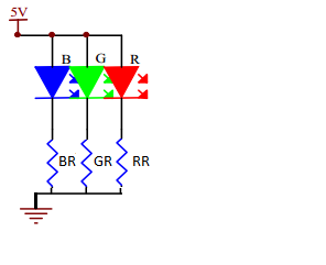
5V Power and 1 RGB LED
In this configuration the voltage dropping resistors for the LED are integrated into the control chip
and the excess power heats the chip.

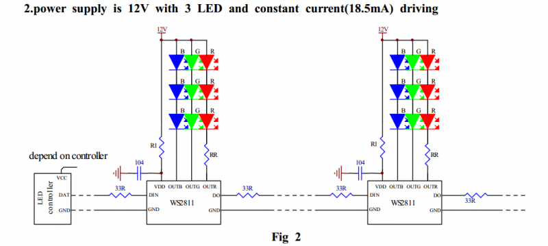
12V Power and 3 RGB LEDs
In this configuration the voltage dropping resistors for the Green and Blue LED are integrated into the control chip and the excess power heats the chip. The Red LED requires a separate external current limiting resistor. Typical resistor values for R1 is 2.7K Ω and RR is 240 Ω

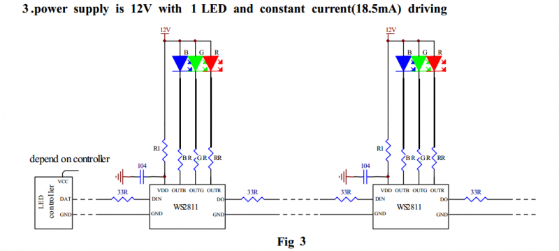
12V Power and 1 RGB LED
In this configuration, all three LED require separate external current limiting resistors and the excess power heats both the control chip and the IC.

Voltage Drop and Power Loss in Wire
In high current and low voltage systems like Pixels and Dumb RGB it is critical to use the SHORTEST length of THICK (low gauge) wire to minimize voltage drop. Wire like Cat5 is just too thin for most uses.
It is desirable to use the largest wire diameter (smaller wire gauge AWG) that you can when connecting your pixels to your controller. The higher wire gauge results in a higher voltage drop and can cause your pixels to have poor colors or to not function at all. The voltage drop is caused by the resistance in the wire and is calculated by Ohm's Law. This is a good thread that discusses voltage drop.
This is a Voltage Drop Calculator useful for calculating the effects of different wire sizes and lengths on pixel strings as well as pixel spacing and wire used in the strings themselves..
The voltage drop occurs in three major areas:
- Power wires from the Power Supply to the Pixel Controller
- Power wires from the Pixel Controller to the Pixel string/strip
- Power wires in the Pixel string/strip
A simple example is how you choose the right size wire between the Pixel Controller and the Pixel string/strip. You can use the data from the table below to estimate your voltage drop based on the current and wire gauge you will be using. For example:
- What is the voltage drop for a string of 5VDC pixels that draw 3A that have a 10ft length of Cat 5 Wire (24 gauge) between the beginning of the string and the controller?
The total resistance of the wire would be (10 foot)*(25.67x10⁻³) = 0.2567 ohms, but since the current goes down one wire and returns on the second wire, you need to double the resistance, so the total loop resistance is 0.5134 ohms.
By Ohm's Law we know that V=IR, so the voltage drop is V = (3A) * (0.5134 ohms) = 1.5402 V So instead of your pixels getting 5V they are only getting 5 - 1.5402 = 3.4598V a drop of 31%! Your pixels would not work ... - What is the voltage drop for the same string of pixels that have a 10ft length of 22 gauge wire between the beginning of the string and the controller?
The total resistance of the wire would be (10 foot)*(16.14x10⁻³) = 0.1614 ohms, but since the current goes down one wire and returns on the second wire, you need to double the resistance, so the total loop resistance is 0.3228 ohms.
By Ohm's Law we know that V=IR, so the voltage drop is V = (3A) * (0.3228 ohms) = 0.9684 V So instead of your pixels getting 5V they are only getting 5 - 0.9684 = 4.0316V a drop of 20%! Getting better, but still not good. - What is the voltage drop for the same string of 5VDC pixels that have a 10ft length of 18 gauge wire between the beginning of the string and the controller?
The total resistance of the wire would be (10 foot)*(6.39x10⁻³) = 0.0639 ohms, but since the current goes down one wire and returns on the second wire, you need to double the resistance, so the total loop resistance is 0.1278 ohms.
By Ohm's Law we know that V=IR, so the voltage drop is V = (3A) * (0.1278 ohms) = 0.3834 V So instead of your pixels getting 5V they are only getting 5 - 0.3834 = 4.6166V a drop of only 8%! That may work for short strings of pixels. - What is the voltage drop for the same string of 5VDC pixels that have a 5ft length of 18 gauge wire between the beginning of the string and the controller?
The total resistance of the wire would be (5 foot)*(6.39x10⁻³) = 0.0320 ohms, but since the current goes down one wire and returns on the second wire, you need to double the resistance, so the total loop resistance is 0.0640 ohms.
By Ohm's Law we know that V=IR, so the voltage drop is V = (3A) * (0.0640 ohms) = 0.1917 V So instead of your pixels getting 5V they are only getting 5 - 0.1917 = 4.8083V a drop of only 4%! Short thick wires are the answer!
When you factor in the voltage drop due to the wire in the pixel strings themselves ( a harder calculation, use the calculator mentioned above) the final pixels at the end of the string may not have enough voltage to light or function properly.
A classic symptom of the voltage being too low at the end of a pixel string is the pixels may look Pink instead of White when turned on fully White. If the color of the first pixel in a string is different from the last pixel in the string, it is likely due to the voltage drop in the string and the wires supplying it. This is why folks often use Power Injection at the end of the pixel strings to boost the voltage to the pixels at the very end of the string. You should always use the largest diameter wire you have available (smaller gauge) to connect your pixels with the controller and to use for power injection.
If all you have is higher gauge wire, it is possible to double or triple up the wires (use 2 or 3 parallel wires for the V+ and Ground) to help reduce the effective wire resistance.
The following data is from http://www.powerstream.com/Wire_Size.htm Load Carrying Capacities (see table below)
"The following chart is a guideline of ampacity or copper wire current carrying capacity following the Handbook of Electronic Tables and Formulas for American Wire Gauge. As you might guess, the rated ampacities are just a rule of thumb. In careful engineering the voltage drop, insulation temperature limit, thickness, thermal conductivity, and air convection and temperature should all be taken into account. The Maximum Amps for Power Transmission uses the 700 circular mils per amp rule, which is very very conservative. The Maximum Amps for Chassis Wiring is also a conservative rating, but is meant for wiring in air, and not in a bundle. For short lengths of wire, such as is used in battery packs you should trade off the resistance and load with size, weight, and flexibility. NOTE: For installations that need to conform to the National Electrical Code, you must use their guidelines. Contact your local electrician to find out what is legal! "
| Properties of Copper Conductors | ||||||
| AWG Gauge | Conductor Diameter Inches |
Conductor Diameter mm |
Ohms per foot |
Ohms per meter |
Maximum Amps for Chassis Wiring |
Maximum Amps for Transmission |
|---|---|---|---|---|---|---|
| 8 | 0.1285 | 3.2639 | 0.63x10⁻³ | 2.06x10⁻³ | 73 | 24 |
| 10 | 0.1019 | 2.58826 | 1.00x10⁻³ | 3.28x10⁻³ | 55 | 15 |
| 12 | 0.0808 | 2.05232 | 1.59x10⁻³ | 5.21x10⁻³ | 41 | 9.3 |
| 14 | 0.0641 | 1.62814 | 2.53x10⁻³ | 8.28x10⁻³ | 32 | 5.9 |
| 16 | 0.0508 | 1.29032 | 4.02x10⁻³ | 13.17x10⁻³ | 22 | 3.7 |
| 18 | 0.0403 | 1.02362 | 6.39x10⁻³ | 20.94x10⁻³ | 16 | 2.3 |
| 20 | 0.032 | 0.8128 | 10.15x10⁻³ | 33.29x10⁻³ | 11 | 1.5 |
| 22 | 0.0254 | 0.64516 | 16.14x10⁻³ | 52.94x10⁻³ | 7 | 0.92 |
| 24 | 0.0201 | 0.51054 | 25.67x10⁻³ | 84.20x10⁻³ | 3.5 | 0.577 |
| 26 | 0.0159 | 0.40386 | 40.81x10⁻³ | 133.86x10⁻³ | 2.2 | 0.361 |
Overall 12VDC Pixels are more tolerant of voltage drop because the reduction in voltage that takes place does not begin to effect the LEDs as rapidly as it does at 5VDC for pixels drawing the same current. Since several 12VDC pixels actually run at lower current (10ma per color vs 20ma per color) and voltage drop is directly related to current, 12VDC low current pixels are the most tolerant to voltage drop and allow the longest wires between the pixels and the controllers.
Related Links
Different Styles of Pixels
Controllers
Dumb RGB or Intelligent Pixels??
Things You Will Need To Get Started With Pixels
Pixel Wiring Colors
Power Supplies
Pixel Connectors
Power Injection
Waterproofing Pixels
Null Pixels
E1.31 Network Setup and Configuration
