Disclaimers
The standard disclaimers pertaining to the information contained on this wiki page are listed here.
Pixel/RGB Wiring Colors
Pixels generally have 3-4 wires connected to each pixel:
- +5 or +12VDC Power Feed
- Ground Power Feed
- Data/ Signal
- Clock (not on all pixels)
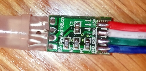
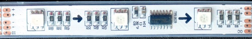
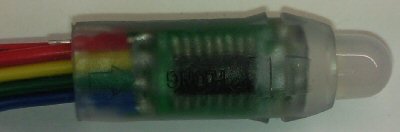
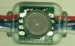
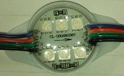
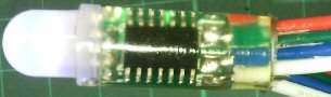
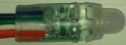
Because pixels are sending control signals down the wires, there is an input set of wires and an output set of wires coming from each pixel. You can generally find markings such as words or arrows that identify the data direction for each set of wires by looking closely at the printed circuit board inside of the pixel. Other clues may include individual pin markings such as "SDO" Serial Data Output, "SDI" Serial Data Input, "CKO" Clock Output or "CKI" Clock Input. it is common to have the power on the two outer wires on a pixel and the data and clock as the inside wires. Many strings come two ground wires connected to the input and output sides.
Unfortunately there is no standard wiring color code for pixels supplied by different manufacturers.
DIYLEDEXPRESS.COM Pixels
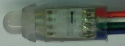
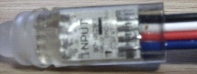
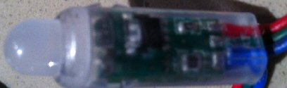
WS2811 Pixabulbs
WS2811 Pixelabulb Strings (Input is end of string with male connector)
| Ground
|
Data
|
+12V
|
Photo
|
| Black
|
Green
|
Red
|
PICTURE TBD
|
WS2811
WS2811 Pixel Strings (input is not chip side)
| Ground
|
Data
|
+5V
|
Photo
|
| Blue (GND)
|
White (DI)
|
Red (+5v)
|
PICTURE TBD
|
WS2801
WS2801 Pixel Strings (input is chip side)
| Ground
|
Clock
|
Data
|
+5V
|
Output Side Photo
|
| Blue (GND)
|
Green (CKO)
|
White (SDO)
|
Red (+5v)
|
|
TM1809
TM1809 Pixel Strip
| +12V
|
Ground
|
Data
|
Photo
|
| Red (+)
|
Blue (-)
|
Green (DI/DO)
|
|
Other Vendors
Thanks to http://www.auschristmaslighting.com for this great info.
WS2801
WS2801 Pixel Strings (input is non-chip side usually)
| Scheme
|
+5V
|
0V
|
Clock
|
Data
|
Photo
|
| 1
|
Red
|
Blue
|
White
|
Black
|
|
| 2
|
Red
|
White
|
Green
|
Blue
|
|
| 3
|
Red
|
Blue
|
Green
|
Yellow
|
|
| 4
|
Red
|
Yellow
|
Blue
|
Green
|
|
| 5
|
Black
|
White
|
Red
|
Blue
|
|
Sources:
- Fasteddy
- Blickensderfer
- ThaiWay
- Stella Black
- JPB
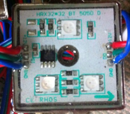
TM1804
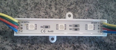
TM1804 Pixel Module (Square)
| Signal
|
Wire Colour
|
Marking
|
|
| +12V
|
Red
|
+12V
|
| Data
|
Green
|
DI
|
| 0V
|
Blue
|
GND
|
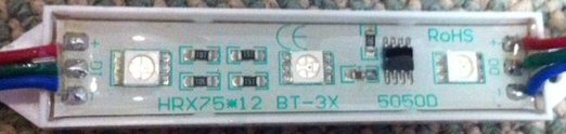
TM1804 Pixel Module (Rectangular)
| Signal
|
Wire Colour
|
Marking
|
|
| +12V
|
Red
|
+
|
| Data
|
Green
|
DI
|
| 0V
|
Blue
|
-
|
TM1804 Pixel Strings (Input is on chip side)
| Signal
|
Wire Colour
|
|
| +12V
|
Red
|
| 0V
|
Green
|
| Data
|
Blue
|
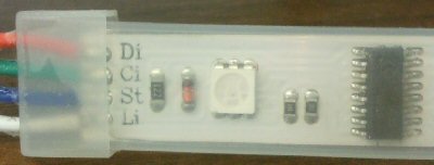
LPD6803
LPD6803 Pixel Strip
| Signal
|
Wire Colour
|
Marking
|
|
| +12V
|
Red
|
Di
|
| Data
|
Green
|
Ci
|
| Clock
|
Blue
|
St
|
| 0V
|
White
|
Li
|
LPD6803 Pixel String (RGB order)
| Signal
|
Wire Colour
|
|
| +5V
|
Red
|
| 0V
|
Yellow
|
| Data
|
Green
|
| Clock
|
Blue
|
LPD6803 Pixel String (GRB order)
| Signal
|
Wire Colour
|
|
| +5V
|
Red
|
| Data
|
Green
|
| Clock
|
Blue
|
| 0V
|
White
|
LPD6803 Pixel String (RGB order)
| Signal
|
Wire Colour
|
|
| 0V
|
Blue
|
| Clock
|
Red
|
| Data
|
Green
|
| +24V
|
Black
|
P9813
P9813 Pixel String (BGR order) Input is on chip side
| Signal
|
Wire Colour
|
|
| +5V
|
Red
|
| Data
|
Green
|
| Clock
|
Blue
|
| 0V
|
White
|
DC (No IC)
DC RGB Pixel String
| Signal
|
Wire Colour
|
|
| Blue
|
Blue
|
| Green
|
Green
|
| +5
|
White
|
| Red
|
Red
|
DC RGB Module (input Left Hand Side)
| Signal
|
Wire Colour
|
|
| +12
|
Yellow
|
| Green
|
Green
|
| Red
|
Red
|
| Blue
|
Blue
|
GECE Wiring
http://sandevices.com/documents/GE_Pixel_Wiring.pdf
Related Links
Different Styles of Pixels
Controllers
Dumb RGB or Intelligent Pixels??
Things You Will Need To Get Started With Pixels
Power Supplies
Pixel Connectors
Choosing a Pixel Voltage: 5V vs 12V
Power Injection
Waterproofing Pixels
Null Pixels
E1.31 Network Setup and Configuration


