Renard 64XC: Difference between revisions
| (18 intermediate revisions by 2 users not shown) | |||
| Line 1: | Line 1: | ||
=='''Introduction'''== | =='''Introduction'''== | ||
[[Image:REN64 XC | [[Image:REN64 XC.jpg|center|650px]] | ||
The Renard 64 is a PIC microcontroller based Christmas light controller designed to be used with external Solid State Relays or SSRs. The board design is based on the PIC-based 8-port dimmer concept originally developed by Phil Short. Information on the original concept can be viewed [http://computerchristmas.com/christmas/link-how_to/HowToId-71/Simple_PIC-Based_8-Port_Dimmer here]. Generic information pertaining to current Renard designs (including maximum channel count) can be found on the [[Renard]] wiki page. | The Renard 64 is a PIC microcontroller based Christmas light controller designed to be used with external Solid State Relays or SSRs. The board design is based on the PIC-based 8-port dimmer concept originally developed by Phil Short. Information on the original concept can be viewed [http://computerchristmas.com/christmas/link-how_to/HowToId-71/Simple_PIC-Based_8-Port_Dimmer here]. Generic information pertaining to current Renard designs (including maximum channel count) can be found on the [[Renard]] wiki page. | ||
For some reason, many people view the Renard 64 as an "advanced" board. I could not disagree more. This is a very basic, easy to assemble board. And, with the channel LEDs, gives you instant feedback on what should be going on with your lights. The largest problem to date has been the lack of documentation. This new page is the first step in changing that perception! | For some reason, many people view the Renard 64 as an "advanced" board. I could not disagree more. This is a very basic, easy to assemble board. And, with the channel LEDs, gives you instant feedback on what should be going on with your lights. The largest problem to date has been the lack of documentation. This new page is the first step in changing that perception! | ||
Now, why build a Renard 64XC controller vs. all the other Renard Designs? Well, the Renard 64XC control system is a "star" type system. This means, that the main controller stays in a central location while the SSRs are on the tips of the "spokes" similar to that of the FireGod System. The real savings in this layout is in the power cables. Most of the channel power cables are very short. This system is very good for widely spaced display items with small groups of channels in one area like mini-trees. | |||
[[Image:Renard_64_Layout.gif|center]] | |||
In the above diagram, all the wiring in blue and red is CAT5 cable. The only place that the main power needs to be run to is each SSR. Now for clarity, only SSR 9 is shown with individual channels. This power cable is shown in black. Compared to an onboard Renard design, the Renard 64XC needs just about the same number of power cables, but the overall length is reduced to a bare minimum. This design does use copious amounts of CAT5 cable...but of the two, its the cheapest!. | |||
The previous versions, XA and XB, and the original wiki version of XC can be found [[Renard64 | here]] | The previous versions, XA and XB, and the original wiki version of XC can be found [[Renard64 | here]] | ||
| Line 17: | Line 21: | ||
[[Image:renard64_xc5b.gif|center]] | [[Image:renard64_xc5b.gif|center]] | ||
The Renard 64 measures 6.5" x 5" and is available tyically year around from [http://doityourselfchristmas.com/forums/member.php?u=11 wjohn]. | The Renard 64 measures 6.5" x 5" and is available tyically year around from [http://doityourselfchristmas.com/forums/member.php?u=11 wjohn]. He also sells the bare PCB in his [http://www.xmasinmelb.com/zencart/index.php?main_page=product_info&cPath=1&products_id=1 store]. | ||
=='''Circuit Diagram'''== | =='''Circuit Diagram'''== | ||
| Line 77: | Line 81: | ||
=='''Bill of Materials'''== | =='''Bill of Materials'''== | ||
<pre> | <pre style="font-size: 10pt"> | ||
Note: This BOM does not include a transformer, power cords or connectors for the primary side of the transformer. | |||
Note: This BOM does not include a transformer, power cords or | |||
connectors for the primary side of the transformer. | |||
PCB | PCB | ||
| Line 112: | Line 118: | ||
1 538-22-03-2021 Molex PCB Header 2-pin JP1 | 1 538-22-03-2021 Molex PCB Header 2-pin JP1 | ||
1 151-8000 2-Pin Shunt JP1 | 1 151-8000 2-Pin Shunt JP1 | ||
1 538-39890-0302 2 Position Terminal (replaces Tab1/2) | 1 538-39890-0302 2 Position Terminal (replaces Tab1/2) Tab1/Tab2 | ||
2 571-1-390261-2 8 Pin Economy IC Socket | 2 571-1-390261-2 8 Pin Economy IC Socket U4, U5 | ||
1 571-1-390261-1 6 Pin Ecomony IC Socket | 1 571-1-390261-1 6 Pin Ecomony IC Socket U6 | ||
ICs | ICs | ||
| Line 127: | Line 133: | ||
1 520-TCH1843-X Oscillator, 18.432 MHz, 5V, 8-DIP U3 | 1 520-TCH1843-X Oscillator, 18.432 MHz, 5V, 8-DIP U3 | ||
Optional (if per/port LEDs are desired | Optional (if per/port LEDs are desired...However, these are also used as the Diagnostic | ||
LEDs as well...STRONGLY SUGGESTED) | |||
64 859-LTL-403G *LEDs, Rectangular, Green | 64 859-LTL-403G *LEDs, Rectangular, Green | ||
8 652-4608X-1LF-680 *Resistor Network, 680 Ohm, 8-Pin, Bussed R10-13, R20-23 | 8 652-4608X-1LF-680 *Resistor Network, 680 Ohm, 8-Pin, Bussed R10-13, R20-23 | ||
| Line 133: | Line 141: | ||
*Items marked (*) are optional and up to the user. However, they are strongly encouraged. | *Items marked (*) are optional and up to the user. However, they are strongly encouraged. | ||
</pre> | </pre> | ||
| Line 141: | Line 150: | ||
Renard 64 XC BOM Revision History | Renard 64 XC BOM Revision History | ||
<pre style="font-size: 10pt"> | |||
2008/01/21 PJS DE9 connector (J22) added to BOM | |||
2008/01/25 PJS changed value of R1, R2 to 750 Ohm (was improperly calculated for 6.3VAC input). | |||
2008/02/18 PJS changed value of C1 | |||
2010/08/13 JCF changed part number of C1 due to end of life, Replaced Tab1/2 w/2 Pos. Terminal, Added sockets for U4, U5 | |||
and U6, made DE9 connector optional, added optional heat sink for U1. | |||
</pre> | |||
=='''Firmware'''== | =='''Firmware'''== | ||
| Line 186: | Line 197: | ||
:'''Data cables for Renard 64 board hookup directly to computer COMM port''' | :'''Data cables for Renard 64 board hookup directly to computer COMM port''' | ||
[[image:DE9toDE9_Renard.gif | 900px |center]] | [[image:DE9toDE9_Renard.gif | 900px |center]] | ||
<pre style="font-size: 10pt"> | |||
PC DE9 Pin 3 to Renard 64XC JDP1 Pin 3 | PC DE9 Pin 3 to Renard 64XC JDP1 Pin 3 | ||
PC DE9 Pin 5 to Renard 64XC JDP1 Pin 5 | PC DE9 Pin 5 to Renard 64XC JDP1 Pin 5 | ||
</pre> | |||
[[image:DE9toRJ45_Renard.gif | 900px|center ]] | [[image:DE9toRJ45_Renard.gif | 900px|center ]] | ||
<pre style="font-size: 10pt"> | |||
PC DE9 Pin 3 to RJ45-pin 4 | PC DE9 Pin 3 to RJ45-pin 4 | ||
PC DE9 Pin 5 to RJ45-pin 5 and pin 1 and/or pin 2 | PC DE9 Pin 5 to RJ45-pin 5 and pin 1 and/or pin 2 | ||
</pre> | |||
| Line 200: | Line 215: | ||
[[image:RS485toRJ45_Renard.gif | 900px |center]] | [[image:RS485toRJ45_Renard.gif | 900px |center]] | ||
<pre style="font-size: 10pt"> | |||
RS485 Adapter Pinouts | RS485 Adapter Pinouts | ||
RS485(-) Signal to RJ45-pin 4 | RS485(-) Signal to RJ45-pin 4 | ||
| Line 213: | Line 229: | ||
RJ45 connector pin 2 (Data-) to RJ45-pin 4 | RJ45 connector pin 2 (Data-) to RJ45-pin 4 | ||
RJ45 connector pins 7 & 8 (GND) to RJ45-pins 1 & 2 | RJ45 connector pins 7 & 8 (GND) to RJ45-pins 1 & 2 | ||
</pre> | |||
:'''Data cable for Renard 64 board hookup to other Renard boards''' | :'''Data cable for Renard 64 board hookup to other Renard boards''' | ||
| Line 236: | Line 252: | ||
:::* You only need one instance of the Renard Dimmer plug-in in Vixen for each physical COMM port being used. You just need to make sure that the plug-in is setup for the total number of channels for all the Renard boards connected to that COMM port. In the above example, the plug-in would be set for 176 channels. | :::* You only need one instance of the Renard Dimmer plug-in in Vixen for each physical COMM port being used. You just need to make sure that the plug-in is setup for the total number of channels for all the Renard boards connected to that COMM port. In the above example, the plug-in would be set for 176 channels. | ||
:::* The total number of Renard boards that can be connected together depends on the event period and the baud rate being used. More information on the total number of channels capable with Renard systems can be found | :::* The total number of Renard boards that can be connected together depends on the event period and the baud rate being used. More information on the total number of channels capable with Renard systems can be found [[Renard#Number of Circuits (Channels) | here.]] | ||
=='''Computer Setup'''== | =='''Computer Setup'''== | ||
| Line 281: | Line 297: | ||
[[Category:DIYC Controllers]] | |||
[[Category:Renard]] | |||
[[Category:Renard 64XC]] | [[Category:Renard 64XC]] | ||
[[Category:Renard64]] | [[Category:Renard64]] | ||
[[Category: | [[Category:DIYC Index]] | ||
Latest revision as of 02:19, 11 July 2013
Introduction
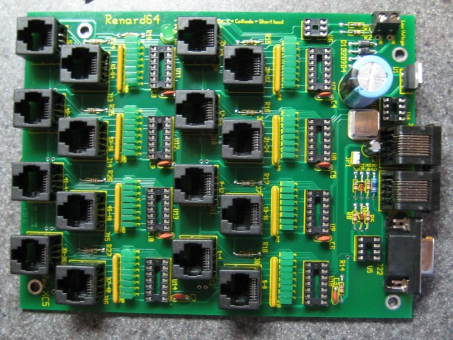
The Renard 64 is a PIC microcontroller based Christmas light controller designed to be used with external Solid State Relays or SSRs. The board design is based on the PIC-based 8-port dimmer concept originally developed by Phil Short. Information on the original concept can be viewed here. Generic information pertaining to current Renard designs (including maximum channel count) can be found on the Renard wiki page.
For some reason, many people view the Renard 64 as an "advanced" board. I could not disagree more. This is a very basic, easy to assemble board. And, with the channel LEDs, gives you instant feedback on what should be going on with your lights. The largest problem to date has been the lack of documentation. This new page is the first step in changing that perception!
Now, why build a Renard 64XC controller vs. all the other Renard Designs? Well, the Renard 64XC control system is a "star" type system. This means, that the main controller stays in a central location while the SSRs are on the tips of the "spokes" similar to that of the FireGod System. The real savings in this layout is in the power cables. Most of the channel power cables are very short. This system is very good for widely spaced display items with small groups of channels in one area like mini-trees.
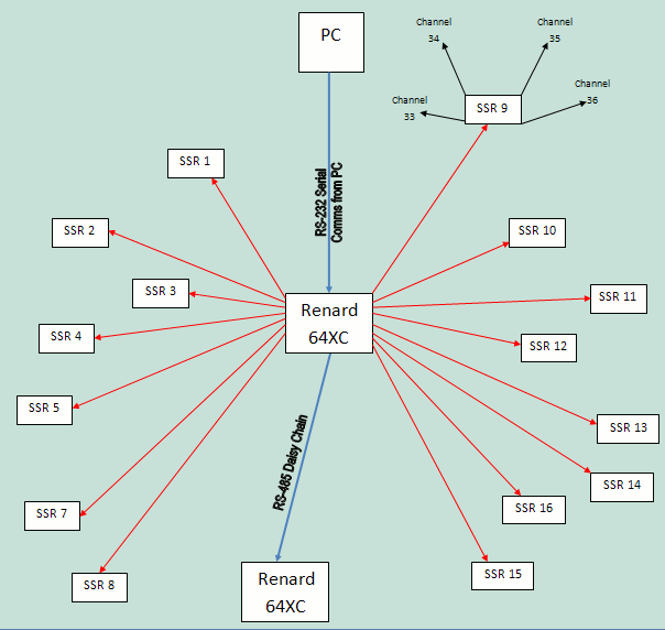
In the above diagram, all the wiring in blue and red is CAT5 cable. The only place that the main power needs to be run to is each SSR. Now for clarity, only SSR 9 is shown with individual channels. This power cable is shown in black. Compared to an onboard Renard design, the Renard 64XC needs just about the same number of power cables, but the overall length is reduced to a bare minimum. This design does use copious amounts of CAT5 cable...but of the two, its the cheapest!. The previous versions, XA and XB, and the original wiki version of XC can be found here
Disclaimers
- The standard disclaimers pertaining to the information contained on this wiki page are listed here.
The Board
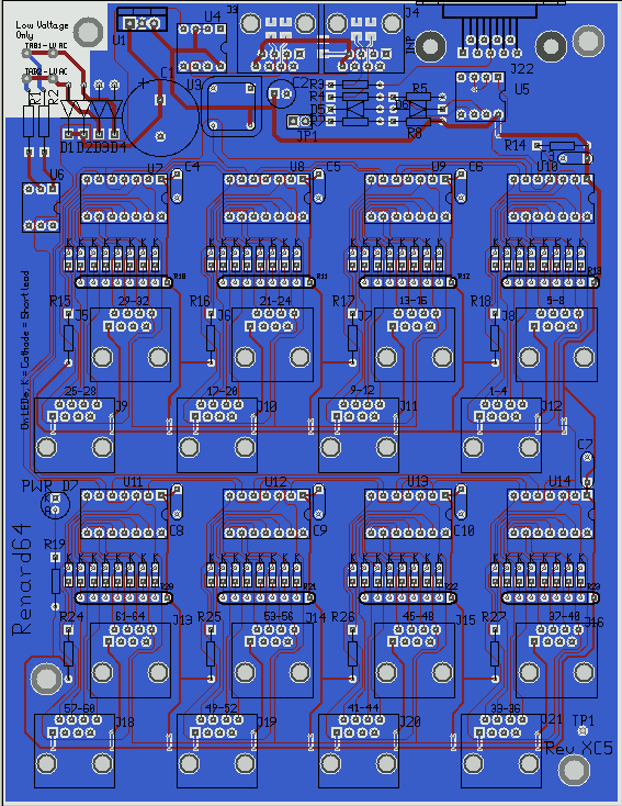
The Renard 64 measures 6.5" x 5" and is available tyically year around from wjohn. He also sells the bare PCB in his store.
Circuit Diagram
- The schematic diagram can be found here.
- Key circuit components
- Connectors
- J3 – RS485 outgoing data
- J4 – RS232/RS485 incoming data (RS485 with JP1 Shunted)
- J5 - Output Connector for Channels 29-32
- J6 - Output Connector for Channels 21-24
- J7 - Output Connector for Channels 13-16
- J8 - Output Connector for Channels 5-8
- J9 - Output Connector for Channels 25-28
- J10 - Output Connector for Channels 17-20
- J11 - Output Connector for Channels 9-12
- J12 - Output Connector for Channels 1-4
- J13 - Output Connector for Channels 61-64
- J14 - Output Connector for Channels 53-56
- J15 - Output Connector for Channels 45-48
- J16 - Output Connector for Channels 37-40
- J18 - Output Connector for Channels 57-60
- J19 - Output Connector for Channels 49-52
- J20 - Output Connector for Channels 41-44
- J21 - Output Connector for Channels 33-36
- J22 – RS232 incoming data, DE9 connector for direct connect to show computer serial port.
- Connectors
- IC Chips
- U6 – H11AA1 Optocoupler, used to generate the Zero Cross signal
- U4 & U5 – RS232/RS485 Transmitter/ Receiver
- U7-U14 – PIC Microcontrollers
- IC Chips
- Resistors
- R10-R13, R20-R23 – Channel LED Current Limiting Network (x7)resistors.
- R15-18, R24-R27 - Channel LED Current Limiting Resistor.
- Resistors
- LEDs
- PWR – Lit whenever the voltage regulator is generating 5 VDC.
- LEDs
- When U10 is programmed with the Diagnostic Firmware:
- Channel 2 LED - will blink ON/OFF to indicate that the PIC is operating correctly.
- Channel 5 LED - will blink ON/OFF to indicate that the Zero Cross signal is getting to the PIC correctly.
- Channel 6 LED - will be ON whenever the PIC is receiving data correctly.
- Channel 7 LED - will only be ON when the PIC has identified a Framing Error while receiving data.
- Channel 8 LED - will only be ON when the PIC has identified an Overrun Error while receiving data.
- Other Components
- U1 – Voltage Regulator
- U3 – Crystal Clock Oscillator
- Other Components
- Jumpers
- JP1 – RS232 signal ground. Install a shunt (jumper) on JP1 when receiving RS232 data.
- Jumpers
- Test Points
- +5 – Output from voltage regulator, should be +5 ± 0.1 VDC. This can be best measured at the U1 lead next to U4. However, it is the easiest to measure at the input to Resistor R8, next to U5.
- GND – The Ground test point is labeled TP1 and is found at the lower right hand corner of the board as shown above.
- Test Points
Bill of Materials
 Note: This BOM does not include a transformer, power cords or
connectors for the primary side of the transformer.

PCB
1  TBA                   Renard 64-Port PCB

Resistors

2  299-750-RC            750 Resistor, 1/8 W, Axial                  R1,R2
1  660-MF1/4DCT52R1200F  120 Resistor, 1/4 W, Axial                  R3
3  299-27K-RC            27K Resistor, 1/8 W, Axial (RS485 pull)     R5,R8,R14
2  299-1K-RC             1K Resistor, 1/8 W, Axial (RS485 series)    R4,R7
1  299-330-RC            330 Resistor, 1/8 W, Axial (for power LED)  R19

Capacitors

1  667-ECA-1CM682        6800 uF, 16V Radial-Lead Elect. Cap         C1
8  80-C322C104K5R        0.1 uF Radial-lead Ceramic Capacitor        C3-C10
1  647-UVR1C470MDD       47 uF, 16V Radial-Lead Elect. Cap           C2

Diodes
4  625-1N5817-E3         Schottky Diode (20V, 1A)                    D1-D4
1  78-1N5229B            4.3v 0.5w Zener                             D5
1  78-1N5239B            9.1v 0.5w Zener                             D6
1  604-WP7104GT          T1 Green LED                                D7

Connectors

2  571-5520251-4         AMP Modular Jacks, Right Angle              J3, J4
16 571-5556416-1         AMP Modular Jacks, Vertical PCB mount       J5-16, J18-21
1  636-182-009-213R531   *Norcomp DE9 Female Rt Angle D-sub Conn     J22
8  575-199314            14 Pin Low Profile IC Socket                U7-U14
1  538-22-03-2021        Molex PCB Header 2-pin                      JP1
1  151-8000              2-Pin Shunt                                 JP1
1  538-39890-0302        2 Position Terminal (replaces Tab1/2)       Tab1/Tab2
2  571-1-390261-2        8 Pin Economy IC Socket                     U4, U5
1  571-1-390261-1        6 Pin Ecomony IC Socket                     U6

ICs

1  511-L4940V5           Regulator, LDO, 5V, 1.5A                    U1
1  532-577102B00         *Heat Sink                                  U1
2  511-ST485BN           RS485 Connectors                            U4,U5
1  782-H11AA1            Optoisolator                                U6
8  579-PIC16F688-I/P     PIC16F688, DIP14, Industrial Temp           U7-14

Oscillator
1 520-TCH1843-X          Oscillator, 18.432 MHz, 5V, 8-DIP           U3

Optional (if per/port LEDs are desired...However, these are also used as the Diagnostic
LEDs as well...STRONGLY SUGGESTED)

64 859-LTL-403G          *LEDs, Rectangular, Green
8  652-4608X-1LF-680     *Resistor Network, 680 Ohm, 8-Pin, Bussed    R10-13, R20-23
8  299-680-RC            *Resistor, 680 Ohm, 1/8W                     R15-18, R24-27

*Items marked (*) are optional and up to the user.  However, they are strongly encouraged.
BOM For Mouser
This link, Mouser REN64XC BOM , is to a live REN64XC bill of materials already loaded into Mouser's system. You just need to put it in your shopping cart. It contains all the optional components listed as well as a 115VAC-->6.3VAC transformer. This is the recommended configuration.
Note: The REN64XC and the optional transformers (see AC Power below for details) fit very well in the CG-1000 Cable Demarc Enclosure from YBBS.
Renard 64 XC BOM Revision History
2008/01/21  PJS DE9 connector (J22) added to BOM
2008/01/25  PJS changed value of R1, R2 to 750 Ohm (was improperly calculated for 6.3VAC input).
2008/02/18  PJS changed value of C1
2010/08/13  JCF changed part number of C1 due to end of life, Replaced Tab1/2 w/2 Pos. Terminal, Added sockets for U4, U5
and U6, made DE9 connector optional, added optional heat sink for U1.
Firmware
- The PICs (U7 - U14) must be programmed with the latest firmware for the Renard 64 to operate properly. The firmware can be found on the Renard Firmware wiki page.
Powering the Renard 64
- Input power requirements: An AC source of 6.3VAC
DC power:
- The Renard 64XC generates all the DC voltage that it requires on-board and no external DC voltage source is required.
AC Power:
- The board is designed to be powered with a 6.3VAC, 1A transformer, providing both power and a zero-crossing signal at the same time. One potential transformer for this application is the Xicon 41FD010 transformer (mouser p/n 41FD010). The center-tap of this transformer should be left open, perhaps covered with a wire nut to protect it from inadvertant short-circuits.
- If all the LEDs are used in the REN64XC, a 1000mA could be used if all the channels were used. This leaves no room for error on the transformer listed above. One option is to use a 41FD030 which is a 3A version of the transformer listed above. Now the interesting thing is, at the time of this writing, the 41FD030 is actually cheaper than the smaller one. It is not a good idea to power more than one board off a single transformer.
- If you do not have 120VAC power, then you may have a larger challenge. A cost effective transformer from 220VAC to 6.3VAC has not been located. There are options but you should get some expert assistance from forums members. Careful selection of resistor replacements with special care to the overall maximum input voltage is required and each case is special. Several members have located a 9VAC secondary. This is about the maximum that can be used safely due to the voltage rating on the ripple capacitor C1. The R1 and R2 values should be changed to 1.2k Ohm for this particular situation. If you cannot locate a secondary less than 9VAC, then you need to change C1 to a 25V capacitor. They are available...just cost more.
Hooking Up the Renard 64
Data Connections
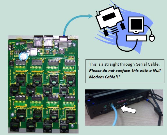
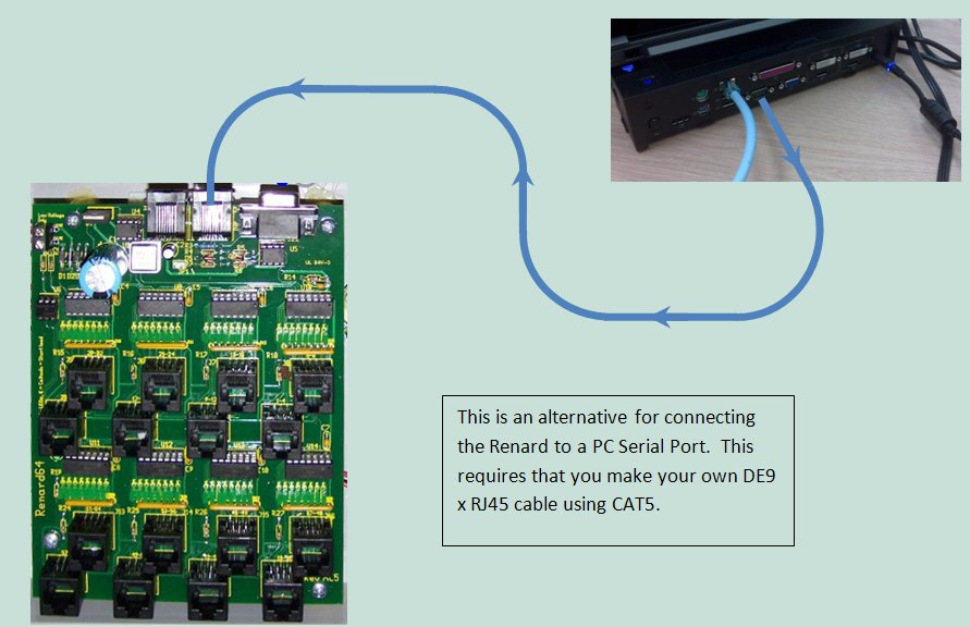
Data Cables
- Data cables for Renard 64 board hookup directly to computer COMM port
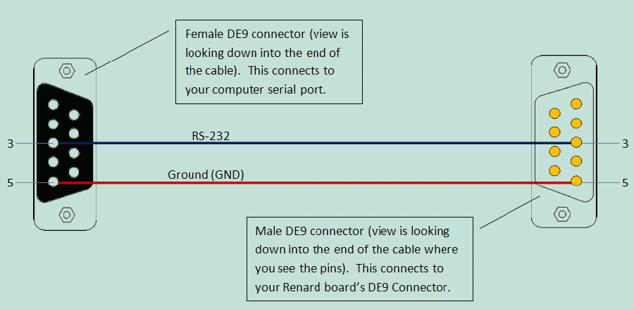
 PC DE9 Pin 3 to Renard 64XC JDP1 Pin 3
 PC DE9 Pin 5 to Renard 64XC JDP1 Pin 5
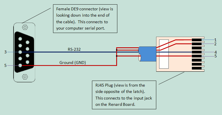
 PC DE9 Pin 3 to RJ45-pin 4
 PC DE9 Pin 5 to RJ45-pin 5 and pin 1 and/or pin 2
- Data cable for Renard 64 board hookup using a RS232->RS485 converter or DMX Adapter
- Due to the many different types of RS232->RS485 converters available the drawing only refers to the signals coming from the converter. Check the documentation for your converter to figure out how/where to hook up the correct wires.
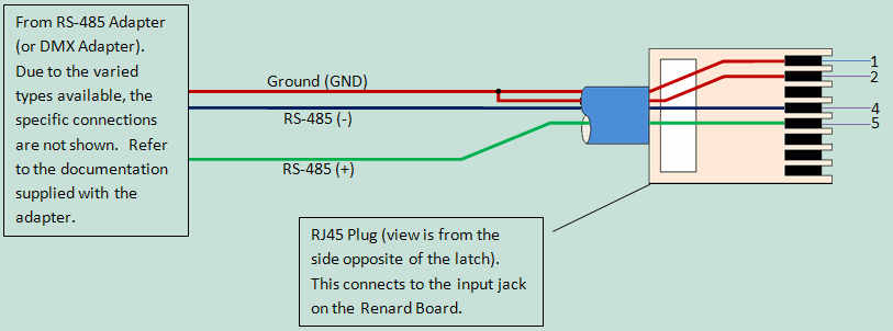
 RS485 Adapter Pinouts
    RS485(-) Signal to RJ45-pin 4
    RS485(+) Signal to RJ45-pin 5

 DMX via XLR Connectors - Pinouts
    XLR connector pin 1 (GND) to RJ45-pin 1 and/or pin 2
    XLR connector pin 2 (Data-) to RJ45-pin 4
    XLR connector pin 3 (Data+) to RJ45-pin 5

 DMX via RJ45 Connectors - Pinouts
    RJ45 connector pin 1 (Data+) to RJ45-pin 5
    RJ45 connector pin 2 (Data-) to RJ45-pin 4
    RJ45 connector pins 7 & 8 (GND) to RJ45-pins 1 & 2
- Data cable for Renard 64 board hookup to other Renard boards
- Generally only a regular straight-thru CAT5 cable is required to connect Renard 64XC boards to other Renard boards. For the few exceptions (ie Ren24 V2.5), check the wiki page for those boards to see what their unique requirements are.
Cable Lengths
- Data cables connecting Renard boards directly to a computer COMM port should not be longer than 50 feet according to the RS-232 standard. This distance can also be greatly reduced by using poor quality cables. However, this distance can be increased buy using high quality, low impedance cables.
- Data cables connecting Renard boards directly to other Renard boards or any other RS-485 source can be up to 4,000 feet in length for data rates up to 100Kbps according to the RS-485 standard.
Connecting Multiple Renard Boards
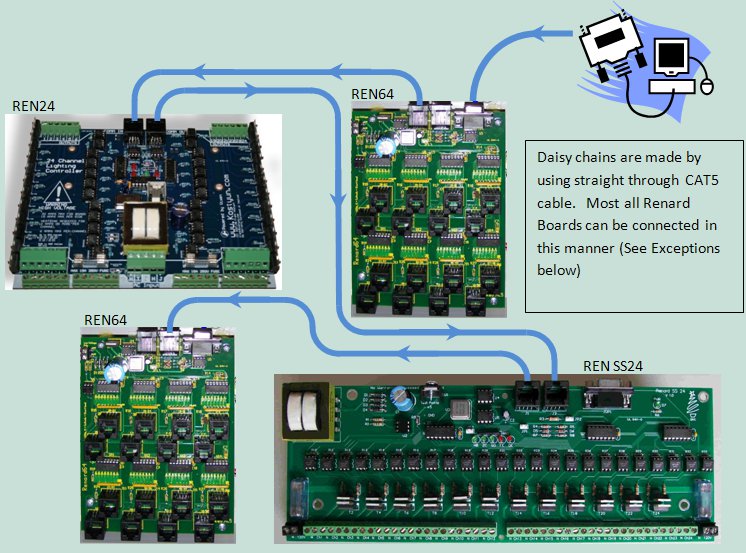
- The above image shows how Renard boards in general can be daisy chained together. Renard 64XC board is connected to the PC Serial Port. This board this then connected to a REN24, a REN SS24 and another REN64. The boards that are used in the image are just an example of how all Renard boards can be connected together. (The XMUS Ren16 and the REN24 v2.5 do have some issues..so read up on them first)
- Key things to remember when connecting ALL Renard boards together:
- You only need one instance of the Renard Dimmer plug-in in Vixen for each physical COMM port being used. You just need to make sure that the plug-in is setup for the total number of channels for all the Renard boards connected to that COMM port. In the above example, the plug-in would be set for 176 channels.
- The total number of Renard boards that can be connected together depends on the event period and the baud rate being used. More information on the total number of channels capable with Renard systems can be found here.
Computer Setup
- VIXEN Settings
- The Renard 64 board requires the Renard Dimmer [Vixen 1.1.*] or Renard Dimmer (modified) [Vixen 2.*] Plug-In.
- Renard Dimmer Plug-In Settings:
- Protocol Version: 1
- COM1 (or whichever COM port you are connected to)
- Baud: 57600 (default firmware value, if firmware is changed then this needs to be changed to match the firmware)
- Parity: None
- Data bits: 8
- Stop bits: One
- Hold port open during the duration of the sequence execution: Checked
- Renard Dimmer Plug-In Settings:
Setup for Beginners and Troubleshooting
- If you are unsure that you have built your hardware correctly, you should follow the procedures contained in the Renard 64XC Beginners Setup Guide.
- If you encounter any problems with your Renard 64XC, you can go to the Troubleshooting Guide The Renard 64XC. The troubleshooting guide contains a methodical process to try to isolate problems/malfunctions and gives suggestions of what to do to fix them.