ESPixel Stick & ESPixel Pops: Difference between revisions
Ukewarrior (talk | contribs) |
Ukewarrior (talk | contribs) |
||
| (212 intermediate revisions by the same user not shown) | |||
| Line 1: | Line 1: | ||
[[Image:Pops_tiny.jpg|right|Version V2]] | |||
[[Image:Pops_board.jpg|right|Version V2]] | |||
==The ESPixel Pops | [[Image:Pixel_Pops_Tiny_Picture_2.jpg|right|Version V2]] | ||
==What is a Pixel Stick?== | |||
The ESPixel stick family of controllers are typically used as Christmas Lighting controllers. | |||
These controllers have two basic characteristics:<br> | |||
1. They control pixel based LED lights<br> | |||
2. They are wireless in terms of their 'data' transfer | |||
==The ESPixel Pops and ESPixel Pops Tiny are variations of the original ESPixel Stick by Shelby Merrick and more specifically a board designed by Bill Porter== | |||
<p> | <p> | ||
The ESPixel Pops is the most basic of the Pixel Stick designs. It is a fully through hole PCB with no smd(surface mount) components. Therefore, it is easily built by most anyone with basic soldering skills | The original "ESPixelStick" is the open source firmware and hardware created by and as a successor to Shelby Merriicks nRF24L01 based PixelStick project. <br> | ||
Bill Porter happened to be working on his Renard ESP and GECE controllers at the same time which also utilize the same ESP8266 ESP-01 module. <br> | |||
Shelby, Bill and a few others have worked since then to broaden functionality and support of the firmware for these devices.<br> | |||
As a result, there is one common firmware thread that works on all of the ESP-01 based DIYC pixel sticks.<br><br> | |||
You can read about this at Bills website found at: [http://www.billporter.info/ The mind of Bill Porter]<br> | |||
You can read further at Shelby's website found at: [http://forkineye.com/ Shelby's Forkineye Website] | |||
<br><br> | |||
The boards discussed in this wiki are derivations of a design by Bill Porter.<br><br> | |||
'''The full discussion thread regarding these boards is found at DIYC at this thread: | |||
[http://doityourselfchristmas.com/forums/showthread.php?47269-Espixel-by-Bill-Porter/page27&highlight=espixel Click Here:]''' | |||
<br><br> | |||
The ESPixel Pops is the most basic of the Pixel Stick designs. It is a fully through hole PCB with no smd(surface mount) components. Therefore, it is easily built by most anyone with basic soldering skills. | |||
This variation was created by Pops Electronics (ukewarrior) in order to create a form factor that would fit inside a 1" thin wall PVC tube. | |||
<br> | |||
<br> | <br> | ||
From a software perspective, it is an E1.31 sACN (Streaming ACN) pixel controller that connects over a standard (802.11g/n) WiFi network. The firmware is open source and developed in the ESP8266 Arduino environment. It provides a web based configuration front-end and currently supports WS2811 / WS2812 pixels. (3-wire pixels) | |||
<br> | |||
</p> | </p> | ||
<p> | <p> | ||
== Pixel Pops & Pixel Pops Tiny == | |||
There are two Pixel Pops boards.<br> | |||
The two boards are '''identical''' in terms of pixel lighting functionality and wiring.<br> | |||
However, the ''TINY'' board is lacking the components to program the ESP-01 module while installed on the Pixel Pops board.<br> | |||
Therefore, if you use the ''TINY'' board, you must have some other mechanism in order to program the ESP-01 module such as the Pops-O-Matic ESP-01 programmer.<br> | |||
[http://www.doityourselfchristmas.com/wiki/index.php?title=Pops-O-Matic_ESP_Programmer#Pops-O-Matic_Overview Pops-O-Matic Info] | |||
== General Features == | == General Features == | ||
[[Image: | [[Image:Built_unit_with_quarter_for_scale.jpg|right|small]] | ||
</p><p> | </p><p> | ||
'''The Pixel Pops has these main features''' </p><p> | '''The Pixel Pops has these main features''' </p><p> | ||
'''1. | '''1. It supports 3 wire pixels such as those based on 2811, 2812 and GECE chipsets'''</p><p> | ||
'''2. | '''2. Supports sACN DMX (E1.31) over 802.11b/g/n Networks'''</p><p> | ||
'''3. | '''3. It utilizes the ESP-01 module for processing and wireless operation''' | ||
<br><br> | <br> | ||
''' | '''4. Supports up to 680 WS2811 or WS2812 Pixels - 4 Universes of DMX data''' <br> | ||
<br><br> | '''5. Supports up to 63 GECE Pixels'''<br> | ||
'''6. It supports both 5v and 12v pixels''' | |||
The board professionally manufactured with 1oz copper and the holes are through plated. This makes for easy and more error free soldering.< | <br> | ||
'''7. The board is small enough to fit inside a 1" thinwall PCB pipe with the PCB measuring only 24.18x33.32 mm and 24.18x24.61 mm for the tiny version. This type of pipe is listed as SDR-21. <br> | |||
Click here for a Lowes example: [https://www.lowes.com/pd/Charlotte-Pipe-1-in-x-10-ft-200-Sdr-21-PVC-Pipe/1000080801 Thin Wall 1" PCV pipe]'''<br> | |||
The board is professionally manufactured with 1oz copper and the holes are through plated. This makes for easy and more error free soldering.<br> | |||
All wires attach via terminal blocks. However, the use of terminal blocks is optional as the holes support direct soldering of wires. | |||
'''The Schematic can be downloaded by clicking on this link: | '''The Schematic can be downloaded by clicking on this link: | ||
[[Media:ESPixel_PopsSchematic.pdf]] | [[Media:ESPixel_PopsSchematic.pdf]] | ||
== Order your own boards == | |||
Contact ukewarrior via a PM on DIYC as he often has boards in stock, cheap ! | |||
'''IF''' ukewarrior is out of boards, you can order them in groups of 3 from OSHPark: | |||
[https://oshpark.com/profiles/PopsElectronics Click here for the Ordering link at OSHPark to order your own boards] | |||
== Fuses == | |||
There is no onboard fuse for the ESPixel Pops. | |||
You can | </p><p> | ||
You can add an inline fuse if desired with the '''input power feed'''. | |||
</p><p> | |||
This can be done very inexpensively with a fuse holder and fuse.<br> | |||
These are available for a total of 34 cents from Tayda Electronics.<br> | |||
Here are the links to those products as of late 2017:<br> | |||
[http://www.taydaelectronics.com/in-line-fuse-holder-for-m205-5x20mm-fuses.html Fuse Holder]<br> | |||
[http://www.taydaelectronics.com/fuse-glass-fast-acting-5a-5x20.html 5A Fuse]<br> | |||
[[File:Purgeme.jpg]] [[Image:glass fuse.jpg|middle|Version V2]] | |||
== Disclaimers == | |||
'''USE the ESPixel Pops board at Your Own Risk !'''</p> | |||
'''The ESPixel Pops board has NO warranty expressed or implied''' | |||
<p> | |||
== BOM - Bill of Materials == | |||
The BOM contains these generically described parts: | |||
- One ESP8266-01, this is not so much a part, but a complete subassembly.<br> | |||
- '''D1''' - One diode. This must be: 1N4148<br> | |||
- '''ESP-01''' - One female socket header, 2 rows of pins, 4 pins in each row. This functions as the socket where you plug the ESP8266 module into<br> | |||
- One six pin header. Readily available 2.54mm (.1") pitch. (distance between the pins)<br> | |||
- One tactile switch. 6mm x 6mm. Also readily available. These often have choices as to the height of the push button.<br> | |||
- '''R1 & R2''' - Two 1/8W or 1/4W carbon film or metal film resistors. 330 Ohms.<br> | |||
- '''C2''' - One polarized Electrolytic capacitor. Any value from 10uF to 220uF will do. 10V or above. Pay special attention to the diameter and spacing of the leads. The diameter can be no more than 5mm and the leads should be spaced at 2mm.<br> | |||
- '''C1''' - One MLCC monolithic capacitor. 2.54mm lead spacing. 0.1uF, any voltage over 24V. (Usually these are 50V rated) These are typically the 'yellow blob' style capacitors, verses the ones that are shaped like a flat disk. These do NOT have a + & - indication, unlike the electrolitic capacitor noted above.<br> | |||
- '''U1''' - One 3.3v voltage regulator. This must be: LD1117V33, which has a TO-220 style package.<br> | |||
- '''IC1''' - One 5.0v voltage regulator. This part is optional and should only be installed if you are planning to drive 12v pixels.<br> | |||
- '''Q1''' - One Mosfet. This must be: 2N7000 or ZVN3306A, which has a T0-92-3 style package<br> | |||
- A five pin screw terminal header. 5 positions total. This connection should have '''3.81mm spacing''' of the mounting pins.<br> | |||
<br> | <br> | ||
<br> | The ESPixel Pops Tiny board has the same BOM but you '''omit''':<br> | ||
- '''D1''' - One diode. This must be: 1N4148<br> | |||
- One tactile switch. 6mm x 6mm.<br> | |||
- One six pin header. Readily available 2.54mm (.1") pitch. | |||
'''One of the DIYC members, beeiilll, constructed BOMs for three vendors.'''<br> They are contained in the thread: | |||
[http://doityourselfchristmas.com/forums/showthread.php?47269-Espixel-by-Bill-Porter/page27&highlight=espixel Click Here:] | |||
Within that thread, you can find the BOMs in these posts:<br> | |||
The BOM's are:<br> | |||
Mouser BOM is in Post #35<br> | |||
Arrow BOM is in Post #48<br> | |||
Digikey BOM is in Post #49<br><br> | |||
'''BOM UPDATE:''' | |||
DIYC member mattd has done some research and created a BOM with some alternate manufacturers.<br> | |||
If you are willing to buy parts with a minimum quantity of 25, he has gotten the per board cost of parts down to $2.41 (not including the ESP-01)<br> | |||
All the details are in the same thread noted above in '''post # 396'''. | |||
Found here: [http://doityourselfchristmas.com/forums/showthread.php?47269-Espixel-by-Bill-Porter&p=490075#post490075 alternative BOM link] | |||
== | == Build Guides == | ||
An extensive build guide for the Pixel Pop Controller and a supplemental guide on how to run DMX based devices from the Pixel Pops has been created by user packebob. | |||
<br> | |||
These can be found on his blog:<br> | |||
[http://zappedmyself.com/projects/espixelpops/ ESPixel Pops Build Guide and DMX enhancement] | |||
== Construction Information == | |||
[[Image:Pixel_pops_both.jpg|right|small]] | |||
The ESPixel Pops is a pretty easy build. The real trick is deciding how you plan to power your pixels as that will affect what you do with the board wiring.<br> | |||
Depending on your power source, this determines if you should install the 5V regulator or just put a jumper in its place as noted on the the board. | |||
The board has a main voltage regulator that provides 3.3V of power to run the ESP8266 module. <br> This module does not care if you are running 5V or 12V pixels. So, you can connect 5V or 12V to the board. | |||
< | |||
The board has a place for a second voltage regulator. This is to accommodate 12V pixels. | |||
<br> | |||
This is location IC1 on the board. This is a spot for either a 5V regulator or a wire jumper.<br> | |||
<br> | |||
'''To summarize the population of the voltage regulators and ICs:'''<br> | |||
The pard labeled: U1 is always installed.<br> | |||
The part labeled: Q1 is always installed.<br> | |||
The part labeled: IC1 is installed if you are running 12V Pixel strings<br> | |||
The part labeled: IC1 is NOT installed if you are running 5V Pixel strings AND you must place a jumper in its place as noted on the board.<br><br> | |||
== Wiring The ESPixel Pops == | |||
[[Image:Pixel_pops_tiny_built_by_Steven_Dill.jpg|right|small]] | |||
[[Image:Pixel_pops_tiny_with_radio_built_by_Steven_Dill.jpg|right|small]] | |||
'''A Key Point Regarding Power'''<br> | |||
The power supply you use must match the voltage requirement of your pixels.<br> | |||
So, if you run 5V pixels, you must have a 5V PS. Same is true for 12V pixels.<br> | |||
'''If you accidentally use a 12V power supply on 5V pixels, you will damage your pixels, perhaps to the extent of destroying the entire string'''. | |||
Along the bottom of the board are 5 connection points. (as viewed from the top...)<br> | |||
The two on the left are for input power.<br> | |||
The three on the right are for pixel connection.<br> | |||
You can either solder on a terminal block or directly solder your wires to the board, or do a mix !<br> | |||
The Terminal block has 3.81mm hole spacing. (The more common 5mm terminal blocks would have made the board too wide)<br> | |||
< | One thing you have to decide is if you will power your pixels through the ESPixel Stick or directly to the Pixel string. (sometimes referenced as "power injection")<br> | ||
It is possible to use the ESPixel Pops as an interface for just the data and run power to the pixels separately.<br> | |||
This is a decision of personal preference and the fact the PCB traces can only handle so much power.<br> | |||
Trial and error is your best approach.<br> | |||
== | == A 3D printed Mount for your Pixel Pops controller == | ||
'''A small Item that you can mount in a cable guard box or other waterproof enclosure'''<br> | |||
User '''amps''' on DIYC created an standoff/mount that can be 3D printed.<br> | |||
The .stl file is available for free on thingiverse at this link:<br> | |||
[https://www.thingiverse.com/thing:4028794 Thingiverse link for Pixel Pops mount]<br> | |||
[[File:Thingaverse.JPG]] | |||
== Programming the ESP-01 Module == | |||
To program the ESP-01, you need to have a board that can load the code.<br> | |||
The ESPixel Pops board can do this, (but not the ''TINY'')<br> | |||
You can also purchase a dedicated programming board.<br> | |||
For example, the Pops-O-Matic programming board is a dedicated ESP-01 programming board. Others are also available.<br> | |||
Information is here: [http://www.doityourselfchristmas.com/wiki/index.php?title=Pops-O-Matic_ESP_Programmer Pops-O-Matic Programmer]<br><br> | |||
The heart and soul of the pixel stick variants is the firmware that runs on the the ESP-01 module.<br> | |||
Work has been done to consolidate to one common set of code.<br> | |||
Shelby Merrick is the keeper (and key cook & bottle washer) of this code.<br> | |||
You | He keeps the current release of code on his github page.<br> | ||
You can find that here: [https://github.com/forkineye/ESPixelStick/releases Pixel Stick Software]<br> | |||
As of 10/30/2017, the current release was version: '''3.0'''<br><br> | |||
As of 11/21/2019, the current release by Shelby that implements dimming control and other features.<br> | |||
You can find that here: [https://github.com/forkineye/ESPixelStick/releases/tag/untagged-725bf24cd612dc3ce18c Pixel Stick Software]<br><br> | |||
' | For Shelby's v3.0 release, there is a Java Flash Tool that you run, enter your SSID and PSK for your wireless network, Pixel, the correct COM port and Upload.<br><br> | ||
'''As of 1/14/2020 Version 3.1 is a Major Update''' Many features including direct support of Webmos & NodeMCU ESP modules. | |||
You can find it here: https://github.com/forkineye/ESPixelStick/releases Pixel Stick Software]<br><br> | |||
https://github.com/forkineye/ESPixelStick/releases | |||
'''Here is a posting by PCpackrat that describes his experience: NOTE: the most current info is at the github webpage noted below...'''<br><br> | |||
this can also be found at this DIYC posting #122 in this thread: [http://doityourselfchristmas.com/forums/showthread.php?40311-ESPixel-GECE-Info-Thread Info Thread]<br><br> | |||
''The firmware is here: https://github.com/forkineye/ESPixelStick | |||
Read through the README.md dont skim like I did. There is a part (gulp) that requires java to 'zip' up the web site information. I just did that part in linux and then copied the files into the data/www folder in the ESPixelStick folder. | |||
Install the prerequisites in README.md | |||
Pay careful attention to the Arduino for ESP8288 version (2.40-rc1). You will have to choose this branch for download. | |||
My short and dirty TL;DR and things I missed: | |||
Modify ssid and passphrase at the top of ESPixelStick.ino | |||
Under Tools: | |||
Choose your board as Generic ESP8266 Module | |||
Flash Size should be 1M (128K SPIFFS) | |||
CPU Frequency 160 MHz | |||
Upload Speed 115200 | |||
Power the unit with the button pressed | |||
Upload the firmware | |||
Remove power from the unit and replug again with the button pressed. | |||
Go to Tools and then ESP8266 Sketch data upload (serial monitor has to be closed for this) | |||
'''To Summarize the whole process:'''<br> | |||
Download the latest Firmware.<br> | |||
Install Java JRE.<br> | |||
Run the ESPSFlashTool.jar once Java is installed.<br> | |||
Configure your settings and let it upload.<br> | |||
Your ESP-01 is now ready to work.<br> | |||
'' | |||
== Pictures of built Pixel Pops boards == | |||
user '''kev''' in California uses Snapple bottles to build a water resistant enclosure for 5 cents | |||
[[File:Pixelpops_enclosure.jpg]] | |||
<br><br> | |||
'''Steven Dill''' uses a Pixel Pops Tiny board enclosed in 1" thin wall PCV to control the coro star on a mega tree. | |||
[[File:Pops_tiny_star.jpg]] | |||
[[File:Pops_tiny_star2.jpg]] | |||
user '''Siconic''' has built both types of boards.<br> | |||
'''If you look closely, you will see that one is constructed for 5V pixels and the other for 12V pixels'''<br> | |||
[[File:Pixel_pops.jpg]] | |||
[[File:Pixel_pops_tiny.jpg]] | |||
[[ | '''Tyson Howard''' mounted his pixel pops in a 3d printed version of https://www.thingiverse.com/thing:1680291 with the inner height changed to 23mm. He then used RTV around the cables coming out of the box. | ||
[[ | [[File:Tysonhoward.jpg]] | ||
[[ | '''David McCauley''' built and created a full pixel display in 2 weeks using pixel pops controllers driven by Falcon Pi Player (FPP)) | ||
[[File:Pixel_pops2.jpg]] | |||
<br><br> | |||
'''William Napier crated these in a few hours as a novice solderer. All worked fine on the first try !'''<br> | |||
[[File:Napier pixel pops.jpeg]] | |||
Latest revision as of 19:32, 22 March 2020
What is a Pixel Stick?
The ESPixel stick family of controllers are typically used as Christmas Lighting controllers.
These controllers have two basic characteristics:
1. They control pixel based LED lights
2. They are wireless in terms of their 'data' transfer
The ESPixel Pops and ESPixel Pops Tiny are variations of the original ESPixel Stick by Shelby Merrick and more specifically a board designed by Bill Porter
The original "ESPixelStick" is the open source firmware and hardware created by and as a successor to Shelby Merriicks nRF24L01 based PixelStick project.
Bill Porter happened to be working on his Renard ESP and GECE controllers at the same time which also utilize the same ESP8266 ESP-01 module.
Shelby, Bill and a few others have worked since then to broaden functionality and support of the firmware for these devices.
As a result, there is one common firmware thread that works on all of the ESP-01 based DIYC pixel sticks.
You can read about this at Bills website found at: The mind of Bill Porter
You can read further at Shelby's website found at: Shelby's Forkineye Website
The boards discussed in this wiki are derivations of a design by Bill Porter.
The full discussion thread regarding these boards is found at DIYC at this thread:
Click Here:
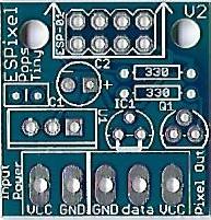
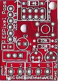
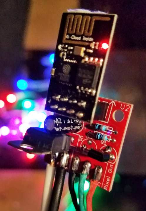
The ESPixel Pops is the most basic of the Pixel Stick designs. It is a fully through hole PCB with no smd(surface mount) components. Therefore, it is easily built by most anyone with basic soldering skills.
This variation was created by Pops Electronics (ukewarrior) in order to create a form factor that would fit inside a 1" thin wall PVC tube.
From a software perspective, it is an E1.31 sACN (Streaming ACN) pixel controller that connects over a standard (802.11g/n) WiFi network. The firmware is open source and developed in the ESP8266 Arduino environment. It provides a web based configuration front-end and currently supports WS2811 / WS2812 pixels. (3-wire pixels)
Pixel Pops & Pixel Pops Tiny
There are two Pixel Pops boards.
The two boards are identical in terms of pixel lighting functionality and wiring.
However, the TINY board is lacking the components to program the ESP-01 module while installed on the Pixel Pops board.
Therefore, if you use the TINY board, you must have some other mechanism in order to program the ESP-01 module such as the Pops-O-Matic ESP-01 programmer.
Pops-O-Matic Info
General Features
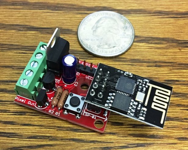
The Pixel Pops has these main features
1. It supports 3 wire pixels such as those based on 2811, 2812 and GECE chipsets
2. Supports sACN DMX (E1.31) over 802.11b/g/n Networks
3. It utilizes the ESP-01 module for processing and wireless operation
4. Supports up to 680 WS2811 or WS2812 Pixels - 4 Universes of DMX data
5. Supports up to 63 GECE Pixels
6. It supports both 5v and 12v pixels
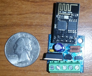
7. The board is small enough to fit inside a 1" thinwall PCB pipe with the PCB measuring only 24.18x33.32 mm and 24.18x24.61 mm for the tiny version. This type of pipe is listed as SDR-21.
Click here for a Lowes example: Thin Wall 1" PCV pipe
The board is professionally manufactured with 1oz copper and the holes are through plated. This makes for easy and more error free soldering.
All wires attach via terminal blocks. However, the use of terminal blocks is optional as the holes support direct soldering of wires.
The Schematic can be downloaded by clicking on this link:
Media:ESPixel_PopsSchematic.pdf
Order your own boards
Contact ukewarrior via a PM on DIYC as he often has boards in stock, cheap !
IF ukewarrior is out of boards, you can order them in groups of 3 from OSHPark: Click here for the Ordering link at OSHPark to order your own boards
Fuses
There is no onboard fuse for the ESPixel Pops.
You can add an inline fuse if desired with the input power feed.
This can be done very inexpensively with a fuse holder and fuse.
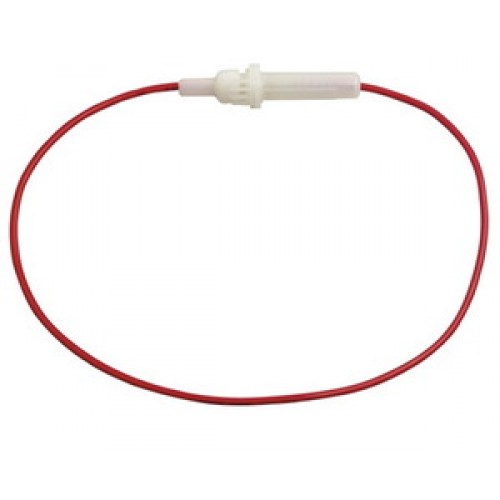
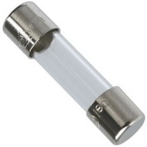
These are available for a total of 34 cents from Tayda Electronics.
Here are the links to those products as of late 2017:
Fuse Holder
5A Fuse
Disclaimers
USE the ESPixel Pops board at Your Own Risk !
The ESPixel Pops board has NO warranty expressed or implied
BOM - Bill of Materials
The BOM contains these generically described parts:
- One ESP8266-01, this is not so much a part, but a complete subassembly.
- D1 - One diode. This must be: 1N4148
- ESP-01 - One female socket header, 2 rows of pins, 4 pins in each row. This functions as the socket where you plug the ESP8266 module into
- One six pin header. Readily available 2.54mm (.1") pitch. (distance between the pins)
- One tactile switch. 6mm x 6mm. Also readily available. These often have choices as to the height of the push button.
- R1 & R2 - Two 1/8W or 1/4W carbon film or metal film resistors. 330 Ohms.
- C2 - One polarized Electrolytic capacitor. Any value from 10uF to 220uF will do. 10V or above. Pay special attention to the diameter and spacing of the leads. The diameter can be no more than 5mm and the leads should be spaced at 2mm.
- C1 - One MLCC monolithic capacitor. 2.54mm lead spacing. 0.1uF, any voltage over 24V. (Usually these are 50V rated) These are typically the 'yellow blob' style capacitors, verses the ones that are shaped like a flat disk. These do NOT have a + & - indication, unlike the electrolitic capacitor noted above.
- U1 - One 3.3v voltage regulator. This must be: LD1117V33, which has a TO-220 style package.
- IC1 - One 5.0v voltage regulator. This part is optional and should only be installed if you are planning to drive 12v pixels.
- Q1 - One Mosfet. This must be: 2N7000 or ZVN3306A, which has a T0-92-3 style package
- A five pin screw terminal header. 5 positions total. This connection should have 3.81mm spacing of the mounting pins.
The ESPixel Pops Tiny board has the same BOM but you omit:
- D1 - One diode. This must be: 1N4148
- One tactile switch. 6mm x 6mm.
- One six pin header. Readily available 2.54mm (.1") pitch.
One of the DIYC members, beeiilll, constructed BOMs for three vendors.
They are contained in the thread:
Click Here:
Within that thread, you can find the BOMs in these posts:
The BOM's are:
Mouser BOM is in Post #35
Arrow BOM is in Post #48
Digikey BOM is in Post #49
BOM UPDATE:
DIYC member mattd has done some research and created a BOM with some alternate manufacturers.
If you are willing to buy parts with a minimum quantity of 25, he has gotten the per board cost of parts down to $2.41 (not including the ESP-01)
All the details are in the same thread noted above in post # 396.
Found here: alternative BOM link
Build Guides
An extensive build guide for the Pixel Pop Controller and a supplemental guide on how to run DMX based devices from the Pixel Pops has been created by user packebob.
These can be found on his blog:
ESPixel Pops Build Guide and DMX enhancement
Construction Information
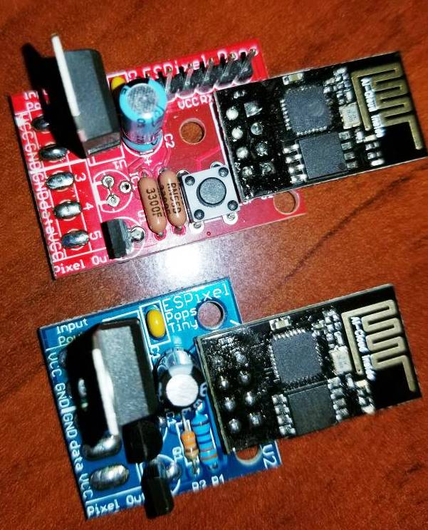
The ESPixel Pops is a pretty easy build. The real trick is deciding how you plan to power your pixels as that will affect what you do with the board wiring.
Depending on your power source, this determines if you should install the 5V regulator or just put a jumper in its place as noted on the the board.
The board has a main voltage regulator that provides 3.3V of power to run the ESP8266 module.
This module does not care if you are running 5V or 12V pixels. So, you can connect 5V or 12V to the board.
The board has a place for a second voltage regulator. This is to accommodate 12V pixels.
This is location IC1 on the board. This is a spot for either a 5V regulator or a wire jumper.
To summarize the population of the voltage regulators and ICs:
The pard labeled: U1 is always installed.
The part labeled: Q1 is always installed.
The part labeled: IC1 is installed if you are running 12V Pixel strings
The part labeled: IC1 is NOT installed if you are running 5V Pixel strings AND you must place a jumper in its place as noted on the board.
Wiring The ESPixel Pops
A Key Point Regarding Power
The power supply you use must match the voltage requirement of your pixels.
So, if you run 5V pixels, you must have a 5V PS. Same is true for 12V pixels.
If you accidentally use a 12V power supply on 5V pixels, you will damage your pixels, perhaps to the extent of destroying the entire string.
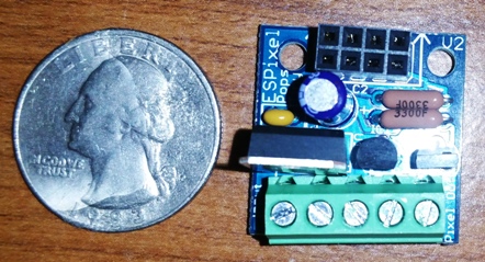
Along the bottom of the board are 5 connection points. (as viewed from the top...)
The two on the left are for input power.
The three on the right are for pixel connection.
You can either solder on a terminal block or directly solder your wires to the board, or do a mix !
The Terminal block has 3.81mm hole spacing. (The more common 5mm terminal blocks would have made the board too wide)
One thing you have to decide is if you will power your pixels through the ESPixel Stick or directly to the Pixel string. (sometimes referenced as "power injection")
It is possible to use the ESPixel Pops as an interface for just the data and run power to the pixels separately.
This is a decision of personal preference and the fact the PCB traces can only handle so much power.
Trial and error is your best approach.
A 3D printed Mount for your Pixel Pops controller
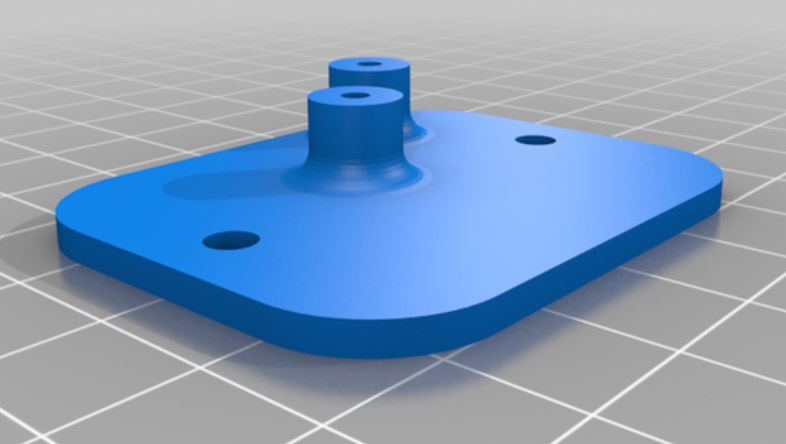
A small Item that you can mount in a cable guard box or other waterproof enclosure
User amps on DIYC created an standoff/mount that can be 3D printed.
The .stl file is available for free on thingiverse at this link:
Thingiverse link for Pixel Pops mount
Programming the ESP-01 Module
To program the ESP-01, you need to have a board that can load the code.
The ESPixel Pops board can do this, (but not the TINY)
You can also purchase a dedicated programming board.
For example, the Pops-O-Matic programming board is a dedicated ESP-01 programming board. Others are also available.
Information is here: Pops-O-Matic Programmer
The heart and soul of the pixel stick variants is the firmware that runs on the the ESP-01 module.
Work has been done to consolidate to one common set of code.
Shelby Merrick is the keeper (and key cook & bottle washer) of this code.
He keeps the current release of code on his github page.
You can find that here: Pixel Stick Software
As of 10/30/2017, the current release was version: 3.0
As of 11/21/2019, the current release by Shelby that implements dimming control and other features.
You can find that here: Pixel Stick Software
For Shelby's v3.0 release, there is a Java Flash Tool that you run, enter your SSID and PSK for your wireless network, Pixel, the correct COM port and Upload.
As of 1/14/2020 Version 3.1 is a Major Update Many features including direct support of Webmos & NodeMCU ESP modules.
You can find it here: https://github.com/forkineye/ESPixelStick/releases Pixel Stick Software]
https://github.com/forkineye/ESPixelStick/releases
Here is a posting by PCpackrat that describes his experience: NOTE: the most current info is at the github webpage noted below...
this can also be found at this DIYC posting #122 in this thread: Info Thread
The firmware is here: https://github.com/forkineye/ESPixelStick
Read through the README.md dont skim like I did. There is a part (gulp) that requires java to 'zip' up the web site information. I just did that part in linux and then copied the files into the data/www folder in the ESPixelStick folder.
Install the prerequisites in README.md
Pay careful attention to the Arduino for ESP8288 version (2.40-rc1). You will have to choose this branch for download.
My short and dirty TL;DR and things I missed:
Modify ssid and passphrase at the top of ESPixelStick.ino
Under Tools: Choose your board as Generic ESP8266 Module Flash Size should be 1M (128K SPIFFS) CPU Frequency 160 MHz Upload Speed 115200
Power the unit with the button pressed
Upload the firmware
Remove power from the unit and replug again with the button pressed.
Go to Tools and then ESP8266 Sketch data upload (serial monitor has to be closed for this)
To Summarize the whole process:
Download the latest Firmware.
Install Java JRE.
Run the ESPSFlashTool.jar once Java is installed.
Configure your settings and let it upload.
Your ESP-01 is now ready to work.
Pictures of built Pixel Pops boards
user kev in California uses Snapple bottles to build a water resistant enclosure for 5 cents
![]()
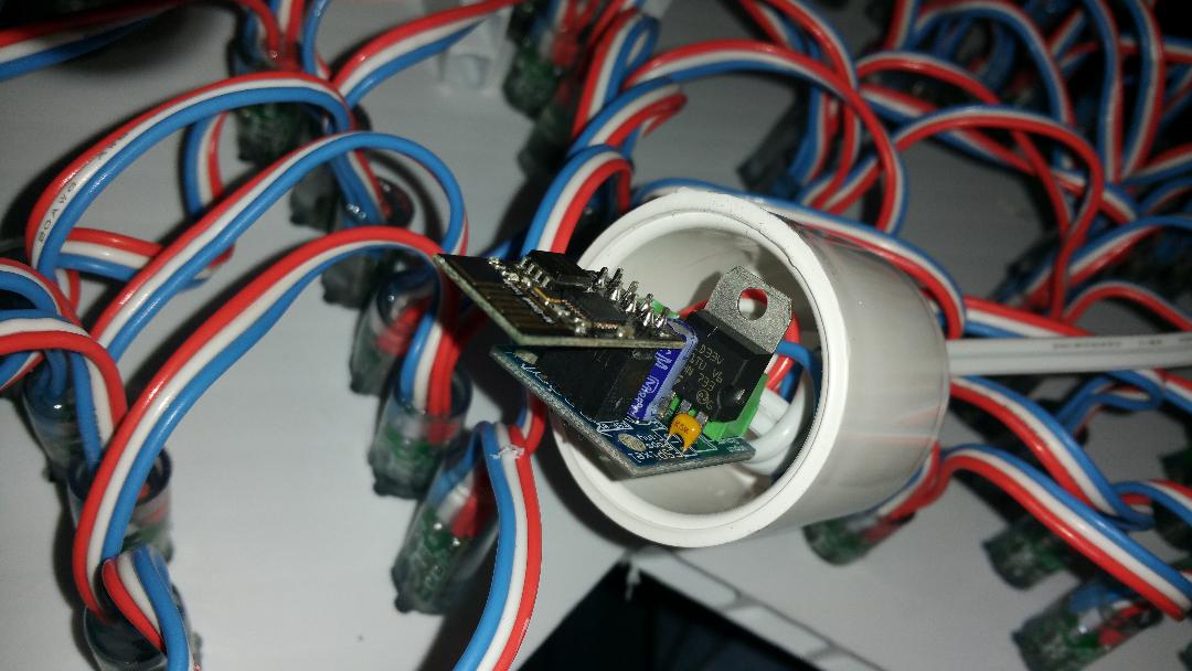
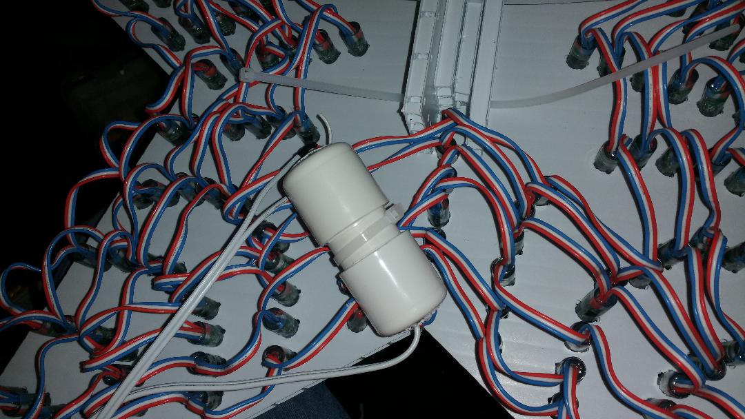
Steven Dill uses a Pixel Pops Tiny board enclosed in 1" thin wall PCV to control the coro star on a mega tree.
user Siconic has built both types of boards.
If you look closely, you will see that one is constructed for 5V pixels and the other for 12V pixels
![]()
![]()
Tyson Howard mounted his pixel pops in a 3d printed version of https://www.thingiverse.com/thing:1680291 with the inner height changed to 23mm. He then used RTV around the cables coming out of the box.
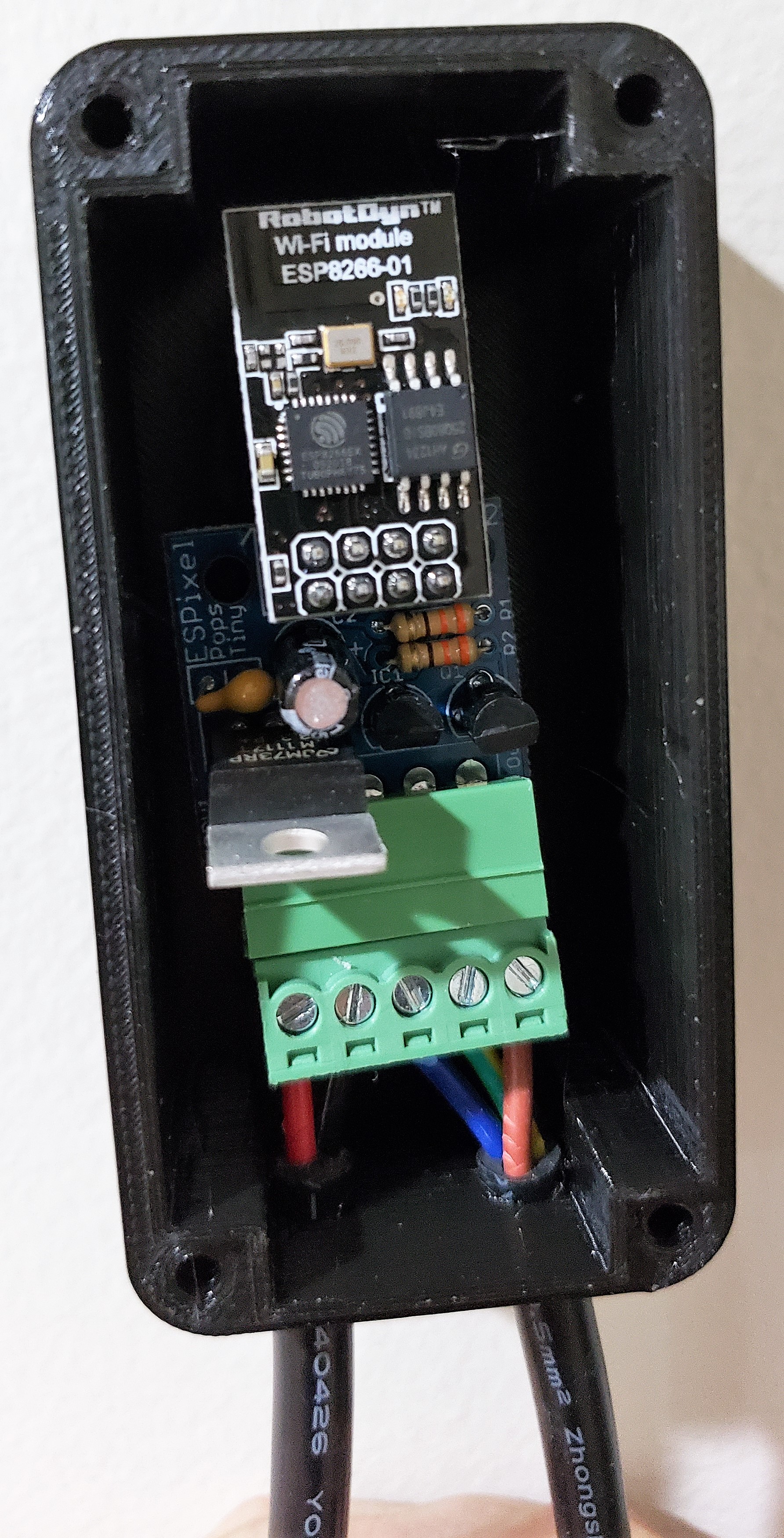 David McCauley built and created a full pixel display in 2 weeks using pixel pops controllers driven by Falcon Pi Player (FPP))
![]()
William Napier crated these in a few hours as a novice solderer. All worked fine on the first try !
![]()