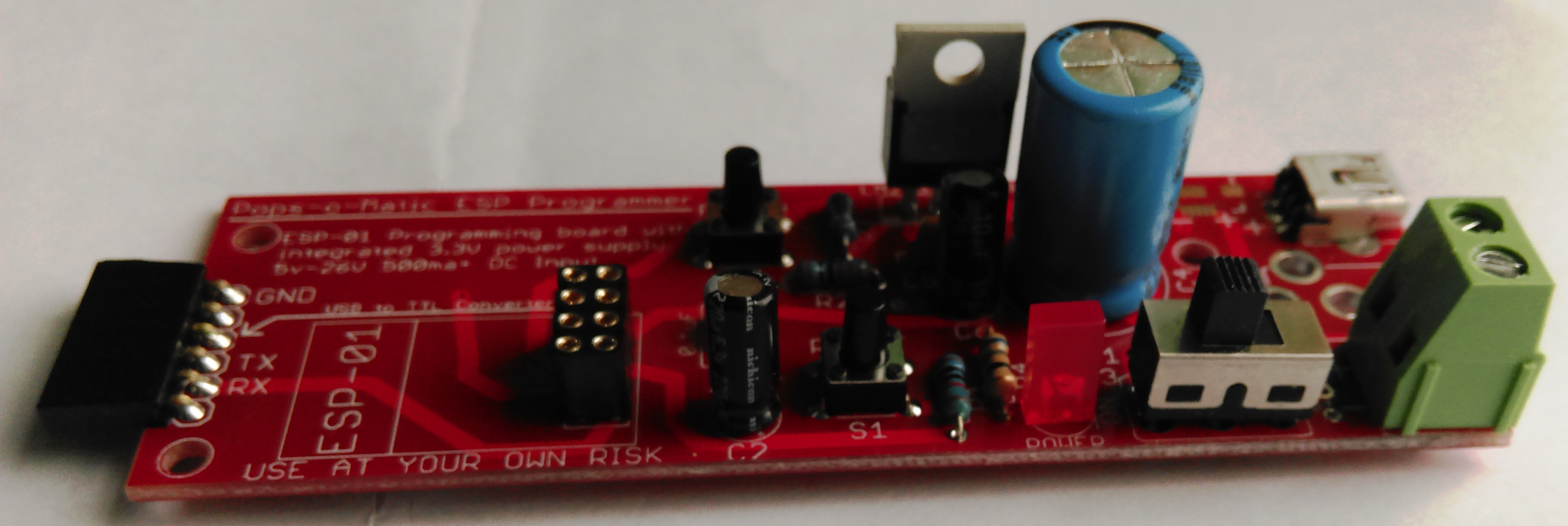
Pops-O-Matic ESP Programmer
What is the Pops-O-Matic ESP Programmer ?
The Pops-O-Matic is a dedicated programming board for the popular ESP-01 module.
This board was inspired from two articles on allaboutcircuits.com. Specifically:
Voltage Regulator
ESP Flashing Circuit
This programming board supplies both the regulated power and the programming interface for the ESP-01 module.
It specifically isolates the ESP-01 from any of the positive power that may be supplied by your serial-to-TTL programmer.
Only Ground, Transmit, and Receive are connected from the external serial-to-TTL programmer to the Pops-O-Matic. (with the assumption you hook it up properly)
The purpose of this is twofold.
1. To protect the ESP-01 module from voltages over 3.3V. (Many TTL programmers are normally run at 5V)
2. To provide the ESP-01 with well regulated and steady power during the programming sequence.
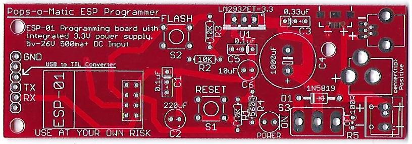
Pops-O-Matic Overview
The Pop-O-Matic is designed to be flexible in assembly and use.
It can take a wide variation of power input voltages (5V-16V) and can support up to 5 different power connections.
The board is designed to use any of the following for a power input connection types:
1. 5mm Terminal Block
2. 3.5mm Terminal Block
3. Micro USB
4. Mini USB
5. Barrel Terminal Jack
The board has a power ON/OFF switch with a power ON LED indicator.
NOTE:
Input power should be at least 400ma.
Order a board
Contact ukewarrior via a PM on DIYC as he often has boards in stock, cheap !
Disclaimers
USE the Pops-O-Matic board at Your Own Risk !
The Pops-O-Matic board has NO warranty expressed or implied
BOM - Bill of Materials
The BOM contains these generically described parts. The SKU at TAYDA electronics (www.taydaelectronics.com) is listed as a reference example following the silkscreen part identifier.
A typical total for these parts is about $3-$4 not including the ESP-01 module and the TTL converter.
Parts U1 & ESP-01 are not sold by TAYDA.
- Input Connectors A-662 - As noted earlier, you have choices for the power input connector. You can populate the board with all the connectors at the same time. The exception to this is that the 3.5mm and 5mm terminal blocks share the same space on the board.
Of course, you can populate it with any combination that suits your fancy, including none at all.
The possible input connectors are: SMD micro USB, through hole mini USB, Terminal Barrel, 3.5mm & 5mm Terminal block.
- S3 A-2001 - Power Switch. SPDT ON-OFF-ON This part is optional. You can short the middle and left holes together to set the board to permanently ON. This SPDT switch has 5mm pin spacing. Most any style will do, both slide and toggle for example.
- D1 A-484 - Diode, specifically 1N5819
- C1 A-214 - MLCC, ceramic Capacitor. 50v, 0.1uF, 2.54mm or 5mm lead spacing.
- C2 A-4506 - Electrolytic Capacitor. 10V, 220uF, 2mm lead spacing, 6mm max diameter.
- C3 A-319 - MLCC, ceramic Capacitor. 50v, 0.33uF, 2.54mm or 5mm lead spacing.
- C4 A-4552 - Electrolytic Capacitor. 25V, 1000uF, 5mm lead spacing, 13mm max diameter.
- C5 A-214 - MLCC, ceramic Capacitor. 50v, 0.1uF, 2.54mm or 5mm lead spacing.
- C6 A-4534 - Electrolytic Capacitor. 25V, 10uF, 2mm lead spacing, 6mm max diameter.
- POWER A-1554 - LED, 5mm, any color.
- R1 A-2203 - 1/4W carbon or metal film resistor. 10K ohm.
- R2 A-2203 - 1/4W carbon or metal film resistor. 10K ohm.
- R3 A-2203 - 1/4W carbon or metal film resistor. 10K ohm.
- R4 A-2282 - 1/4W carbon or metal film resistor. 560 ohm.Note: this resistor is paired with the POWER LED. You should use one of the online calculators to determine the most optimal value given a 3.3V input power to your LED.
- 100R - There is a resistor labeled 100R to the right of the power switch. It is not needed.
- U1 - Voltage Regulator, 3.3V, specifically LM2937ET-3.3, TO-220 package.
- S1 A-5143 - Tactile Switch. 6x6mm through hole.
- S2 A-5143 - Tactile Switch. 6x6mm through hole.
- ESP01 A-1682 - 2x4 femaie pin header. 2.54mm spacing.
- ESP01 - ESP-01 module. This is not actually part of the Pops-O-Matic. It is the board the Pops-O-Matic will help you program.
- USB to TTL A-1384 - A 6 pin header. Either vertical or 90 degree mounting. Male or Female to match the pins on your USB-to-TTL Converter.
- USB to TTL converter A-1991 - This is not actually part of the Pops-O-Matic board, but you will need one if you don't already have one.
The two most popular models are known as the FT232RL and CP2102.
The FT232RL by FTDI was the defacto-standard until they released a code version that would brick peoples PC's in an effort to combat Chinese clones.
This angered a lot of the Maker community. The CP2102 then arose as a competitor to FTDI.
Both of these programmers are available all over the internet, ebay and aliexpress.
You can also order one off of TAYDA as noted.
Construction Information
This board is pretty simple. Just follow typical assembly practices.
Solder from lowest to the board to tallest components last.
Hopefully, you can find some of the parts in your electronics junk drawer stash.
The only reason for five possible power inputs is to match up with whatever is easiest for you use from a power input source.
For example, the usb connections exist to support your typical cell phone charger or any other USB power source. (which is always 5V).
Or you may have an old power brick that has a round terminal barrel connector.
The voltage values of the referenced capacitors can be changed. You can always use a higher voltage capacitor in place of the noted voltage.
Additionally, you may be able to use a lower voltage than what is noted.
i.e. C3 and C4 are on the power input side of the voltage regulator.
If you know FOR SURE that you will never use a voltage over 5V for an input, then these capacitors can be any value above 7.5V and will be just fine. But, if you forget and apply 12V, the caps will let out their magic smoke.
Likewise, capacitors C1, C5 and C6 are after the voltage regulator and will never see a voltage above 3.3V. Therefore, any voltage rating above 5V should be safe.
All this to say is that you can often find a lot of the parts you need for a low voltage board like this in your stash or salvage from other boards.
Errata

The initial board run has one small error.
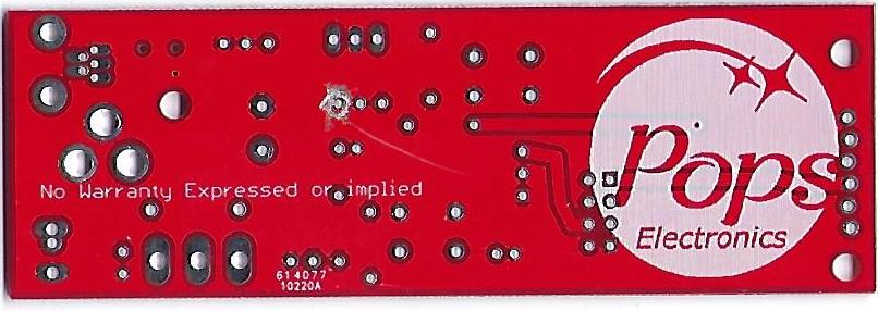
This error has been fixed with the ver 1.1 board. (This version number is noted on the back of the board)
There is an unwanted trace on the back of the board that connects the right most pin (as viewed from the TOP) of part C5 to the ground backplane that covers the bottom of the board.
This unwanted trace should have been placed on the left most pin of C5.
All boards sent out, have had this unwanted trace scraped off the board.
So, the end user doesn't need to do anything to fix this error.
Due to this error, the capacitor for C5 must be mounted using the middle and right most holes only. The left most hole is not connected to anything.
This restriction has been removed with the ver1.1 board
This may cause a problem if your C5 capacitor has 5mm spaced leads. In this case, you would either bend the leads to fit the more narrow spacing,
or you can insert the left most pin through the hole and then bend if over to connect to the middle hole.
In other words, part C5 must have pins touching the middle and right holes. Again, all references are from the top view of the board.


