Renard64: Difference between revisions
Phil Short (talk | contribs) No edit summary |
Phil Short (talk | contribs) Minor reformatting to try and get people to avoid using out-of-date information. |
||
| Line 1: | Line 1: | ||
{{Otheruses4|the XA, XB, and XC versions of the Renard 64|the page about the current version|Renard 64}} | {{Otheruses4|the XA, XB, and XC versions of the Renard 64|the page about the current version|Renard 64}} | ||
==XA and XB PCB Information (non-current revisions)== | |||
=== Schematic=== | === Schematic=== | ||
Revision as of 04:13, 12 December 2010
- This page is about the XA, XB, and XC versions of the Renard 64. For the page about the current version, see Renard 64.
XA and XB PCB Information (non-current revisions)
Schematic
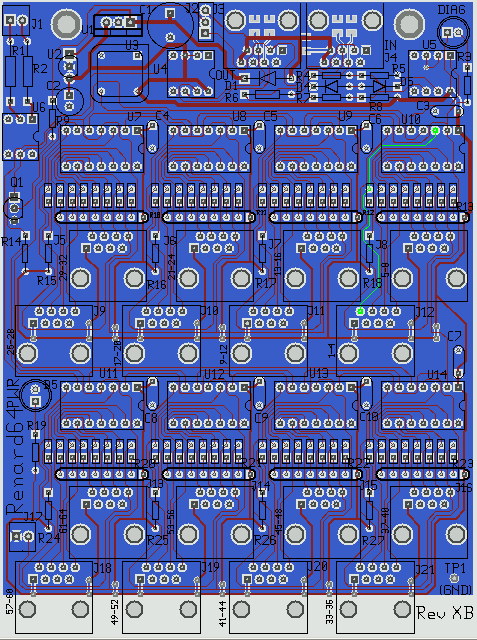
Layout
Important Note: The entire solder side of the PCB is a ground plane, which will tend to absorb and redistribute heat. It is highly recommended that you use a good, temperature controlled soldering iron to assemble the board. Ordinary pen-style soldering irons may not get hot enough to make good solder connections, especially to pins that connect to the ground plane.
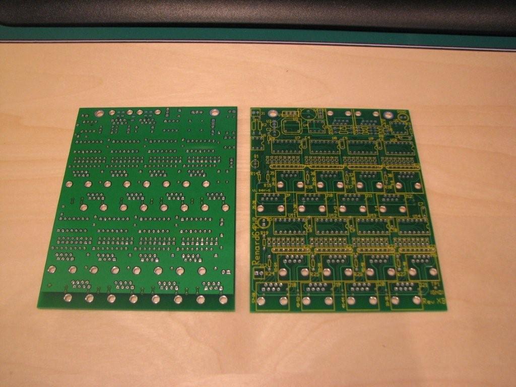
XA PCB
XB PCB
COOP PCB V2.0
BOM for Rev XB Board (old PCB revision)
There are several alternatives listed below for providing a zero-crossing signal. The first choice is listed as preferred, because that is the selection that works with the Ren-T board. The second alternative is OK (requires an external low-voltage transformer). The third alternative will work also, but its use is discouraged because it requires that 110VAC be brought onto the controller board.
NOTE: This BOM is for an older version of the PCB, and is different from the BOM for the current version of the board. You need to scroll down much further to get the current BOM.
PCB
1  TBA                   Renard 64-Port PCB

Resistors

3  299-27K-RC            27K Resistor, 1/8 W, Axial (RS485 pull)     R5,R8,R14
2  299-1K-RC             1K Resistor, 1/8 W, Axial (RS485 series)    R4,R7
1  660-MF1/4DCT52R1200F  120 Resistor, 1/4 W, Axial                  R6
1  299-330-RC            330 Resistor, 1/8 W, Axial (for power LED)  R19

Capacitors

8  80-C322C104K5R        0.1 uF Radial-lead Ceramic Capacitor        C3-C10
1  647-UVR1C470MDD       47 uF, 16V Radial-Lead Elect. Cap           C2

Diodes
1  78-1N5229B            4.3v 0.5w Zener                             D4 (left)
1  78-1N5239B            9.1v 0.5w Zener                             D5 (near R5 on XB) or D4 (right, on XA)
1  604-WP7104GT          T1 Green LED                                D5 (near U11)

Connectors

2  571-5202514           AMP Modular Jacks, Right Angle              J3, J4
16 538-95003-2881        Molex Modular Jacks, Vertical PCB mount     J5-16, J18-21
1  571-640454-2          AMP Polarized Header (2-Pin, Straight Post) J17
8  575-199314            14 Pin Low Profile IC Socket                U7-U14
1  571-1032393           3-Pin Straight Header                       J2
1  151-8000              2-Pin Shunt                                 J2
1  538-70543-0002        3-Pin Shrouded Header (see notes 1-3 below) U1
1  538-50-57-9403        3-Pin SL Connector (mate to preceding item) XU1
3  538-16-02-0103        Crimp Terminals, Female, 22-24AWG, 15μ Au   XU1

ICs

2  511-ST485BN           RS485 Connectors                            U4,U5
8  579-PIC16F688-I/P     PIC16F688, unprogrammed, DIP14, Industrial Temp    U7-14

Oscillator
1 520-TCH1843-X          Oscillator, 18.432 MHz, 5V, 8-DIP           U3

ZC Alternative 1 (if zero-crossing is brought in on J17 or through J3/J4, preferred)
1  299-10K-RC            10K Resistor, 1/8 W, Axial                  R9
1  512-2N3904TFR         2N3904 Transistor                           Q1

ZC Alternative 2 (if 12VAC is brought into J1 as the zero-crossing source)
1  571-640454-2          AMP Polarized Header (2-Pin, Straight Post) J1
1  782-H11AA1            Optoisolator                                U6
2  299-1.5K-RC           1.5K Resistor, 1/8 W    Resistor            R1,R2

ZC Alternative 3 (if 110VAC is brought into J1 as the zero-crossing source, discouraged).
1  571-640454-2          AMP Polarized Header (2-Pin, Straight Post) J1
1  782-H11AA1            Optoisolator                                U6
2  71-CCF60-15K-E3       15K Resistor, 3/4 W, MF Resistor            R1,R2

Optional (if per/port LEDs are desired)
64 859-LTL-403G          LEDs, Rectangular, Green
8  652-4608X-1LF-680     Resistor Network, 680 Ohm, 8-Pin, Bussed    R10-13, R20-23
8  299-680-RC            Resistor, 680 Ohm, 1/8W                     R15-18, R24-27

Optional (if using on-board regulator with unfiltered power brought in through J4, see note 1 below)
1  625-1N5819-E3         50v 1A Schottky Diode                       D1
1  511-L4940V5            Regulator, LDO, 5V, 1.5A                    U1
1  140-XRL16V1000-RC     1000 uF, 16V Radial-Lead Elect. Cap         C1
Note 1: The on-board regulator should only be used if measures are taken to keep the current consumption down (omitting the on-board LEDs, and using the non-PWM firmware). If the LEDs are used and the PWM firmware is installed, the current consumption of the board is about 1A, and so the regulator will dissipate too much power (the small value of C1 precludes decreasing the input voltage). If you are using an external PC power supply, you don't need these optional parts.
If the on-board regulator is used, omit the header that is designated for U1.
Note 2: The specified connectors for bringing in external power are 15μ Gold, you may change this if you have other preferences. Also, the molex calls for using a crimp tool. The ones in the mouser catalog are pretty expensive, and I don't know how well the Radio Shack ones will work.
Note 3: An alternative to the Molex power connectors is to use a modified, spare IDE disk drive Y-cable (or similar) as a pigtail from the board.
Revision History
 7/21/2007 BOM copied from picdimmer forum, on-board regulator made optional
 7/21/2007 Value of regulator parts (diode, regulator, cap) changed.
 7/21/2007 Value of LED current limit resistors changed.
 7/22/2007 Changed p/n of TYCO/Amp vert. mount connector to ROHS, added note about physical size problem with them.
 7/24/2007 Deleted TYCO/Amp vert. mount jacks, they don't fit.  Use the Molex Jacks instead.
 7/24/2007 Changed value of C2, to agree with datasheet for regulator even at low temperatures.
 8/07/2007 Change vendor, pn for optional 680 Ohm resistor network to one that is more readily available.
 8/07/2007 Change description of 299-series resistors (previously had the wrong power rating).
 8/07/2007 Created two zero-crossing alternatives.
 8/12/2007 Added new zero-crossing alternative (the new alternative 2)
 8/27/2007 Added Two 3-Pin headers (for J2, U1) and a 2-pin shunt (J2).
 9/02/2007 Changed two part numbers (added dashes), modified note regarding on-board regulator.
 10/01/2007 Changed part numbers for power connector, added notes regarding that.
 10/01/2007 Fixed incorrect p/n for 3-pin header.
 12/13/2007 Fixed part number on voltage regulator.
Construction Notes
1) The '+' leads of C1 and C2 go in the holes with the square pads.
2) The anodes of the status LEDs (long lead) go in the holes with the square pads.
3) The cathodes (the end with the band) of diodes D1, D4, and D5 go in the holes with the square pads.
4) The pin with the dot above it on the resistor network component should be installed in the square hole.
Errata for Rev XA PCB
 1) The trace between J4 and D1 is too small, and needs to be beefed up if the board is configured to draw more than 1/2A through J4.
 2) There are two diodes labeled D4.
 3) The holes for D1 are too small.
 4) The silkscreen reference designator for C3 (above U10) is missing.
XC PCB Current release
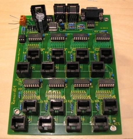
The first prototype, with some parts still to be fitted. Tested on Jan 20, 2008.
Connections
RS232 Input
Over short distances this board can be directly connected to an RS232 serial I/O port. The input cable can be a 9-pin straight-through cable. It should be kept as short as possible, on the order of 20 feet or less. A shunt should be installed between the two pins of JP1 when using an RS232 input source.
However, you can use the RJ45 input connector for RS232 as well. This requires that you make a custom cable from your computer to the first Renard in the chain. This means the the DB9 connector on the BOM can be omitted.
Pin Assignments:
Pin 5 - ground
Pin 3 - serial input signal.
RS485 Input/Output
These connectors may be directly connected to Ren16/Ren24(rev 3.0 and higher) and to other Ren64 board (all versions).
Pinout:
1,2 - ground
4 - RXD+/TXD- (inverting input/output of transceiver)
5 - RXD-/TXD+ (non-inverting input/output of transceiver)
Remove the shunt from JP1 for RS485 input.
Power Input
The board is designed to be powered with a 6.3VAC, 1A transformer, providing both power and a zero-crossing signal at the same time. One potential transformer for this application is the Xicon 41FD010 transformer (mouser p/n 41FD010). The center-tap of this transformer should be left open, perhaps covered with a wire nut to protect it from inadvertant short-circuits.
If all the LEDs are used in the REN64XC, a 1000mA could be used if all the channels were fully on at one time. This leaves no room for error on the transformer listed above. That being said, this is a rare happening given the way we used dimming controllers. One option is to use a 41FD030 which is a 3A version of the transformer listed above. Now the interesting thing is, at the time of this writing, the 41FD030 is actually cheaper than the smaller one. It is not a good idea to power more than one board off a single transformer.
If you do not have 120VAC power, then you may have a larger challenge. A cost effective transformer from 220VAC to 6.3VAC has not been located. There are options but you should get some expert assistance from forums members. Careful selection of resistor replacements with special care to the overall maximum input voltage is required and each case is special. Several members have located a 9VAC secondary. This is about the maximum that can be used safely due to the voltage rating on the ripple capacitor. The R1 and R2 values should be changed to 1.2k Ohm for this particular situation.
Other Connections
Pin 3 of the RJ45 serial input connector J4 is connected to pin 3 of the RJ45 serial output connector J3 with a signal trace.
Pins 7 and 8 of the RJ45 serial input connector J4 is connected to pins 7 and 8 of the serial output connector J3 with a trace capable of carrying 1A or so of current (current capacity to be verified).
Schematic
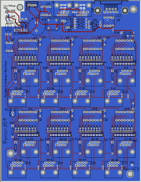
Layout Image
BOM
Note: This BOM does not include a transformer, power cords or connectors for the primary side of the transformer.

PCB
1  TBA                   Renard 64-Port PCB

Resistors

2  299-750-RC            750 Resistor, 1/8 W, Axial                  R1,R2
1  660-MF1/4DCT52R1200F  120 Resistor, 1/4 W, Axial                  R3
3  299-27K-RC            27K Resistor, 1/8 W, Axial (RS485 pull)     R5,R8,R14
2  299-1K-RC             1K Resistor, 1/8 W, Axial (RS485 series)    R4,R7
1  299-330-RC            330 Resistor, 1/8 W, Axial (for power LED)  R19

Capacitors

1  140-XRL16V6800-RC     6800 uF, 16V Radial-Lead Elect. Cap         C1
8  80-C322C104K5R        0.1 uF Radial-lead Ceramic Capacitor        C3-C10
1  647-UVR1C470MDD       47 uF, 16V Radial-Lead Elect. Cap           C2

Diodes
4  625-1N5817-E3         Schottky Diode (20V, 1A)                    D1-D4
1  78-1N5229B            4.3v 0.5w Zener                             D5
1  78-1N5239B            9.1v 0.5w Zener                             D6
1  604-WP7104GT          T1 Green LED                                D7

Connectors

2  571-5520251-4         AMP Modular Jacks, Right Angle              J3, J4
16 571-5556416-1         AMP Modular Jacks, Vertical PCB mount       J5-16, J18-21
1  636-182-009-213R531   Norcomp DE9 Female Rt Angle D-sub Conn      J22
8  575-199314            14 Pin Low Profile IC Socket                U7-U14
1  538-22-03-2021        Molex PCB Header 2-pin                      JP1
1  151-8000              2-Pin Shunt                                 JP1
2  534-4902              Male Sturdi-mount Terminal                  Tab1, Tab2
2  159-2215              Vinyl Insulated Couplers (Female)           Tab1, Tab2

ICs

1  511-L4940V5           Regulator, LDO, 5V, 1.5A                    U1
2  511-ST485BN           RS485 Connectors                            U4,U5
1  782-H11AA1            Optoisolator                                U6
8  579-PIC16F688-I/P     PIC16F688, unprogrammed, DIP14, Industrial Temp    U7-14

Oscillator
1 520-TCH1843-X          Oscillator, 18.432 MHz, 5V, 8-DIP           U3

Optional (if per/port LEDs are desired)
64 859-LTL-403G          LEDs, Rectangular, Green
8  652-4608X-1LF-680     Resistor Network, 680 Ohm, 8-Pin, Bussed    R10-13, R20-23
8  299-680-RC            Resistor, 680 Ohm, 1/8W                     R15-18, R24-27
BOM For Mouser
299-750-RC              2
660-MF1/4DCT52R1200F    1
299-27K-RC              3
299-1K-RC               2
299-330-RC              1
140-XRL16V6800-RC       1
80-C322C104K5R          8
647-UVR1C470MDD         1
625-1N5817-E3           4
78-1N5229B              1
78-1N5239B              1
604-WP7104SGC           1
571-5520251-4           2
571-5556416-1           16
636-182-009-213R531     1
575-199314              8
538-22-03-2021          1
151-8000                1
534-4902                2
159-2215                2
511-L4940V5             1
511-ST485BN             2
782-H11AA1              1
579-PIC16F688-I/P       8
520-TCH1843-X           1
604-WP113GDT            64
652-4608X-1LF-680       8
299-680-RC              8
Note: The REN64XC and the above optional transformers fit very well in the CG-1000 Cable Demarc Enclosure from YBBS.
XC revision History
2008/01/21  PJS DE9 connector (J22) added to BOM
2008/01/25  PJS changed value of R1, R2 to 750 Ohm (was improperly calculated for 6.3VAC input).
2008/02/18  PJS changed value of C1


