Vastelec FM02: Difference between revisions
Ukewarrior (talk | contribs) |
Ukewarrior (talk | contribs) |
||
| Line 30: | Line 30: | ||
[[Image:VAST_FM-02_Display_Board_Dimensions.jpg |right|board dims]] | [[Image:VAST_FM-02_Display_Board_Dimensions.jpg |right|board dims]] | ||
<p></p> | <p></p> | ||
== | == | ||
Revision as of 02:47, 29 September 2011

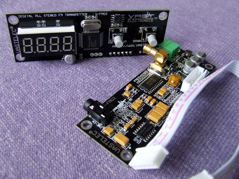
The FM Transmitter with DIY possibilities
Do NOT power it up without an antenna. You don't need to have your 'real' antenna ready for this. You can put the adapter on and then stick a 12" piece of wire into the center of the BNC connector. This will dissipate the RF energy just fine. Just be sure you don't enlarge the hole inside the BNC. DO NOT apply anything GREATER then REGULATED 12V DC to your unit. If you aren't sure, then ask for help in the forums. Use a meter to check the voltage first. If all you have is a wall-wart that is labeled 12V, then that is most likely NOT regulated. A simple test of the output voltage with a meter will tell the tale. I use one of the voltage regulators from Sure Electronics with my unit. These are about $5 online.
About
http://doityourselfchristmas.com/forums/showthread.php?12895-FM02-Transmitter-Setup
Power Requirements
The FM-02 requires a regulated power source of 12V. A power source greater then 12V will damage the board.
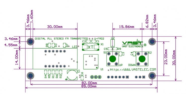
Detailed Board Dimensions
Outline of the 'display' board.

==
This is One board of a two board set. ==
Antenna
http://www.christmasinshirley.com/wiki/index.php?title=File:How_to_make_a_dipole_antenna.pdf