Renard 24LV
Revision 1.0 Board (2008 Co-Op #1)
Schematic
Media:Renard64_sch_001.pdf Please note, the linked schematic is for the Renard 64. The interface for the UNL2803 chips is not included. The addition of the ULN2803 is what requires the REN24LV FW to be changed from the normal one.
Layout
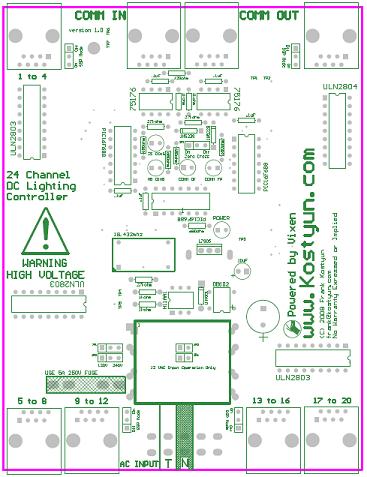
COOP PCB V1.0
Co-Op Board 1.0 Assembly Instructions
The Build Guide for 2.0 can be found here
Board Usage
To run a single high-current LED (for an application such as strobing)
On the board, there are jumpers next to each set of RJ45 jacks. These allow the + voltage on pins 1,3,5,7. By default, it is only on pin 1.
To run the Co-Op SSRs
To run the Co-Op SSRs, a CAT5 cable would be connected to one of the output jacks and run to the SSR input jack.
To run a small string of LED lights
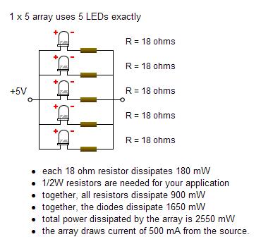
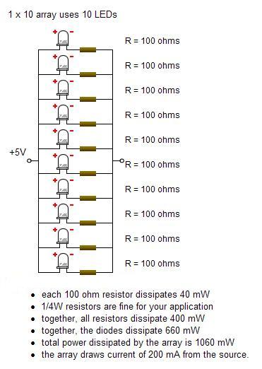
One possible application would be to drive arrays of individual LED strings. With the ULN2803, it is capable of driving up to 500ma per output. (Reccommend using an external +5V power source for this) I would suggest that you can probably run up to 20, 20ma LED's per output, but would reccommend running no more than 100 LED's at once with an external power supply.
In this case, it is using a 5v output from the Ren24 LV, and directly driving the LED's from output of the ULN2803.
On the board, there are jumpers next to each set of RJ45 jacks. These allow the + voltage on pins 1,3,5,7. By default, it is only on pin 1.
This info is based on the LED calculator from linear1.org http://led.linear1.org/led.wiz
Testing the v 1.0 Co-Op Board
There are 7 test points located on the board (TP1 to TP7)
TP1: GND TP2: +5VDC TP3: +12v TP4: 12vac TP5: 12vac TP6: RS485A / RJ45 Pin 5 TP7: RS485B / RJ45 Pin 4
Design Notes for v 1.0 Co-Op Board
Renard 24 Jumper Settings and Options
120/240v Jumpers: Allow for setting the transformers input voltage (labeled as JP1 and JP2.)
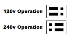
Zero Cross: If on, the board will insert the zero cross signal on the RJ45 pin 3 (labeled as JP3.) This is used to send a ZC signal to another board such as a Ren64 or Ren16.
![]()
12v Jumpers: Located below the transformer, these can be installed to use the board in 12vac only mode (for use with MR16 LED lamps, also labeled as JP5 and JP6.)
Firmware
All Renard Firmware is located Renard_Firmware This board REQUIRES the POSITIVE OUTPUT firmware option. Comment out the following line:
[ #define OUTPUT_NEGATIVE_TRUE] as follows;
[;; #define OUTPUT_NEGATIVE_TRUE]
BOM
1  Ren24 Lv v1.0          Renard 24-Port LV PCB

Board Specific Parts: PLEASE SEE BELOW FOR v3.3 BOARD

595-SN75176BP 2
511-L7805CV 1             '''LM7805 Voltage Regulator'''
821-DB102G 1              '''subsitute part 512-DF01M'''
532-7136DG 1
271-27K-RC 3              '''27k ohm 1/4 watt resistor'''
271-1K-RC 4               '''1k ohm 1/4 watt resistor'''
271-120-RC 1              '''120ohm 1/4 watt resistor'''
625-1N4001-E3 1
78-1N5239B 2
838-3FD-320 1             '''Larger Transformer Reccommended for LV/LED use part 838-3FD-420'''
782-H11AA1 1
520-TCF1843-X 1
140-HTRL25V1000-RC 1
140-HTRL25V10-RC 2
534-3517 2                '''5x20mm Fuse Holder'''
504-GMA-5 1               '''5x20mm 5a fuse'''

Parts from the Common Parts List: (Common parts are the parts that are not unique to the Ren24, and may also be used in other designs) PLEASE SEE BELOW FOR v3.3 BOARD

579-PIC16F688-I/P 3       '''Microchip PIC 16F1688'''
604-WP63ID 4              '''Red T1 3/4 LED, or any 10-30ma LED'''
604-WP1503GD 1            '''Green T1 3/4 LED or any 10-30ma LED'''
271-680-RC 5              '''680ohm 1/4 watt resistor'''
581-SA105E104MAR 5        '''.10 uF Ceramic Capacitor'''
571-9-146281-0 1          '''.100 three pin header(4 needed) Part specified is a 40 pin, cut off size that is needed.'''
571-3828118 8             '''.100 Shunt (4 needed) You may also "steal" these off of old computer parts.'''
571-1-390261-2 2          '''8 pin DIP socket'''
571-1-390261-3 3          '''14 pin DIP socket'''
571-1-390261-5 4          '''18 pin DIP socket'''
571-1-390261-1 1          '''Optional - 6 Pin Socket for H11AA1'''
571-5556416-1 8           '''RJ45 Sockets (8 needed) orientation doesn't matter. This one is top entry.  Use 571-5520251-4 for side entry sockets.'''
571-7969495 1             '''five pin header to jumper both hot sides REPLACES 571-7969494'''
511-ULN2803A 4            '''ULN2803 Darlington Array'''


Optional Parts for The Board:

12VAC Operation
571-9-146281-0 1          '''.100 two pin header(2 needed)'''
571-3828115 4             '''.100 Shunt (2 needed) You may also "steal" these off of old computer parts.'''
838-3FD-320 0             '''Transformer is ELIMINATED from the board in this option'''
The + pin of the DB102 is on the bottom right, both of the ~ should be on the left.
The jumpers on the board are for 120/240v operation. If you don't plan on using the boards on 120v these can be hard soldered with a jumper wire.
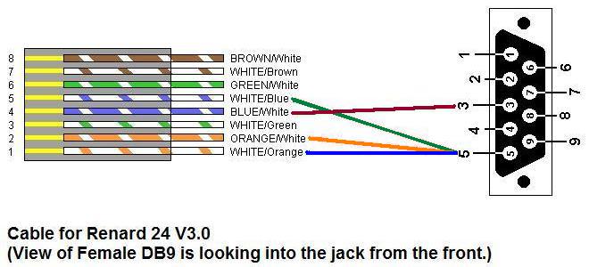
PC to Renard24 LV Cable
PC DB9 Pin 3 to RJ45-pin 4
PC DB9 Pin 5 to RJ45-pins 1,2,5 (pins 1 and 5 are required, pin 2 is optional).
If you are using a RS-232 to RS-485 converter, the pinout is Pin 5 to A+ and Pin 4 to B-. This is the same as for the Ren 16.
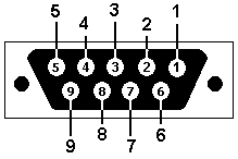 Female DB9 connector as if you were looking into the end of it from the outside.
Renard 24lv Build instructions
Build instructions for the Renard 24lv to include current BOM and instructions for building with an external 24vcd power supply
LINK to build guide here
