Renard PX1 Pixel Controller

General
The Renard PX1 was designed by Phil Short as an inexpensive Pixel controller designed to work with standard Renard systems. It can be daisy chained with other Renard controllers. The PX1 provides a low cost solution that allows a user to add pixels to an existing display setup using just a simple Renard setup.
The design consists of a controller board with a PIC16F1825PIC microcotroller that connects via a simple RS485 connection protocol like all Renard controllers. The PX1 Controller is capable of driving up to 200 pixels per controller (with power injection after 50 pixels) or 50 pixels directly. It supports both 12VDC and 5VDC pixels. The PX1 Controller is designed to support pixels that use the WS2811 and WS2801 IC.
The PX1 is available to purchase anytime. Purchase info is available HERE
Disclaimers
The standard disclaimers pertaining to the information contained on this wiki page are listed here.
THIS BOARD IS STILL IN DEVELOPMENT AND SUBJECT TO CHANGE.
THIS WIKI PAGE IS NOT COMPLETE YET.
Features
- Standard Renard RJ45 (Cat 5 style) data connections
- Capable of driving either 5VDC or 12VDC pixels
- Supports only WS2801 and WS2811 pixels
- Some Design Details:
- One output connector (uses the same 3.5mm Eurostyle connector and pinout as the E682 controller)
- Supports up to 200 pixels per controller with power injection
- Supports up to 50 pixels from the onboard power connection (depends on wire gauge and length)
- Supports both RS232 (Serial) or RS485 input
- Uses the same RJ45 pinout and protocol as standard Renard controllers
- Supports upto 115200 input baudrate from standard Renard Output Plugin
- Uses PIC16F1825 microprocessor, so it can be programed with traditional PICKIT 2 or PICKIT 3 programmers.
- Supports WS2811 strings at with either 400KHz or 800 KHz data rate (Under Development)
- Uses external 5VDC or 12VDC supply (depends on pixel needs)
- Power, RxD (receiving data), FE (framing error)and Attn LED status indicators
- Jumper to select pixel speed (400 KHz vs 800 KHz)(Under Development)
- Designed to fit inside a TA-200 enclosure
Maximum Number of Pixels per Controller
The Renard PX1 can support up to a maximum of 200 pixels per controller. To achieve more then 200 pixels in a Renard system, multiple Renard PX1 pixel controllers must be used. The total number of pixels that may be supported per serial port depends on both the baud rate and on the frequency of updates that has been programmed into the Vixen sequence. The most common PC control software is Vixen, which easily supports multiple serial ports (including USB-RS232 and USB-485 converters). The maximum number of pixels in a Renard system (per comm port) is directly related to the maximum number of channels in a Renard system (per comm port) since each pixel uses 3 channels. The maximum number of pixels is also limited if you are using other controllers in the Renard daisy chain since they use channels and limit the number available for the pixels to use.
| Total Number of Pixels Capable for a given Baud Rate/Refresh Interval* in a Renard Network per Comm Port | |||
| Baud Rate | Refresh Interval | ||
| 100 ms | 50 ms | 25 ms | |
|---|---|---|---|
| 460800* | 1528 | 764 | 382 |
| 230400* | 764 | 382 | 191 |
| 115200 | 382 | 191 | 95 |
| 57600 | 191 | 95 | 47 |
| 38400 | 127 | 63 | 31 |
| 19200 | 63 | 31 | 15 |
The Vixen 2.x Plugin for Renard supports baudrates up to 115200.
*A new Vixen 2.x plugin is required to support higher baudrates.
*The E1.31 Bridge from diyledexpress.com allows baudrates up to 460,800 with a firmware update.
Typical Pixels require power injection every 50 pixels. The Renard PX1 only supports up to 50 Pixels directly powered from the controller. If you use more then 50 Pixels (or if the cable is too long for the wire gauge), you must provide an off-board fused power source to provide Power Injection downstream.
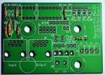
Schematic
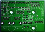
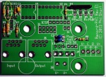
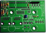
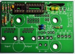
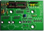
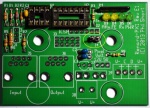
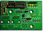
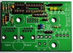
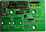
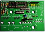
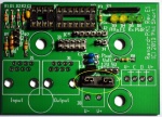
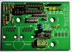
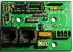
PCB Layout
The current PCB is Rev:E1

BOM - Bill Of Materials
To build Renard PX1 Pixel Controller you will need parts from Mouser and a Renard PX1 Pixel Controller PCB.
Mouser
| Part | Mouser PN | Description | Qty |
| R6 | 291-120-RC | Carbon Film Resistors - Through Hole 120ohms 0.05 | 1 |
| R5,R7 | 299-1K-RC | Carbon Film Resistors - Through Hole 1Kohms 5% | 2 |
| R1,R2 | 299-27K-RC | Carbon Film Resistors - Through Hole 27Kohms 0.05 | 2 |
| R4 | 264-330-RC | Resistor Network, 330 Ohm, Bussed, 6-pin | 1 |
| R3,R8 | 299-47-RC | Carbon Film Resistors - Through Hole 47ohms 0.05 | 2 |
| C2,C3 | 810-FK28X5R1C105K | Multilayer Ceramic Capacitors MLCC - Leaded 1.0uF 16volts X5R +/-10% | 2 |
| C1 | 80-C322C104K5R | Multilayer Ceramic Capacitors (MLCC) - Leaded 50volts 0.1uF 10% X7R | 1 |
| D1 | 78-1N5239B | Diode, Zener 9.1V .5W | 1 |
| D2 | 78-1N5229B | Diode, Zener 4.3V .5W | 1 |
| D3,D4 | 604-WP710A10YT | LED, 3mm Yellow | 2 |
| D5,D6 | 604-WP710A10GT | LED, 3mm Green | 2 |
| IC1 | 595-SN65LBC179PE4 | Buffers & Line Drivers | 1 |
| IC2 | 579-PIC16F1825-I/P | Microcontroller | 1 |
| IC3 | 926-2950CZ-5.0/NOPB | LDO 5.0/100mA | 1 |
| U1 | 571-1-390261-2 | IC & Component Sockets 8P ECONOMY TIN | 1 |
| U2 | 571-1-390261-3 | IC & Component Sockets 14P ECONOMY TIN | 1 |
| J5,J6 | 571-5556416-1 | Jack, Modular RJ45 PCB Mount Top Entry | 2 |
| J4 | 538-22-03-2021 | Headers & Wire Housings VERT PCB HDR 2P TIN PLATING | 1 |
| J3 | 649-77313-122-10LF | Headers & Wire Housings 10P STR DR TMT HDR .76 AU .526IN LENGTH | 1 |
| J2 | 538-22-03-2061 | Headers & Wire Housings VERT PCB HDR 6P TIN PLATING | 1 |
| J1,J7 | 538-22-03-2031 | Headers & Wire Housings VERT PCB HDR 3P TIN PLATING | 2 |
| J8 | 571-2828372 | Fixed Terminal Blocks 5.08MM PCB MOUNT 2P | 1 |
| Jumpers | 151-8000-E | Headers & Wire Housings MINI JUMPER GF 6.0MM OPEN TYPE BLACK | 4 |
| J9 | 538-39501-6004 | Pluggable Terminal Blocks 3.5MM EURO HEADER VE HEADER VERT GRN 4CKT | 1 |
| Pixel Connector | 538-39503-2004 | Pluggable Terminal Blocks 3.50MM EURO PLUG VER UG VERT RWE BLK 4CKT | 1 |
| Fuse | 504-ATM-5 | Fuses 5A 32Vdc 1kA IR Tan | 1 |
| Fuse Holder | 534-3544-2 | Fuse Holder | 1 |
The Mouser Project BOM can be found here. On 07/28/14 the price for a single BOM was $17.34 from Mouser.
Note: If J9 is on backorder, you can substitute 538-39501-1004
If Pixel Connector is on backorder, you can substitute 538-39500-0004, this is an inline plug like the one used with the E682.
Assembly Instructions
Assembly of the Renard PX1 is done in three steps:
- Assemble PCB and Solder parts
- Configure Jumpers
- Program the PIC microcontroller
Renard PX1 Pixel Controller Assembly
Click on photos to see a larger view.
- □ Begin by inspecting the PCBs to look for any defects such as cracks or breaks. The holes on the board should be open on both sides. Then inspect and sort out the various parts for the boards.
- □ Install Resistors
- □ R1,R2 - 27K ohm (red, violet, orange, gold) resistor.
- □ R3,R8 - 47 ohm (yellow, violet, black, gold) resistor.
- □ R5,R7 - 1K ohm (brown, black, red, gold) resistor.
- □ R6 - 120 ohm (brown, red, brown, gold) resistor.
- □ R4 - 330 ohm bussed resistor. Note that this resistor is polarized and only can go in one way. The dot on the package denotes pin1.
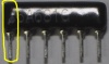
Pin 1 goes in the square hole on the left side.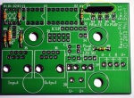
- □ R1,R2 - 27K ohm (red, violet, orange, gold) resistor.
- □ Install Capacitors
- □ C1 - 0.1 uf capacitor. The marking on the capacitor says "104".

It is not polarized and it can go either way.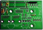
- □ C2,C3 - 1.0uf capacitor. The marking on the capacitor says "105".

It is not polarized and it can go either way.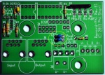
- □ C1 - 0.1 uf capacitor. The marking on the capacitor says "104".
- □ Install Diodes
- □ D1 - 1N5239B diode. Diodes are polarized and they have to be installed with the correct orientation. The end of the diode with the band goes towards the bottom of the board and in the square hole.
- □ D2 - 1N5229B diode. Diodes are polarized and they have to be installed with the correct orientation. The end of the diode with the band goes towards the bottom of the board and in the square hole.
- □ D1 - 1N5239B diode. Diodes are polarized and they have to be installed with the correct orientation. The end of the diode with the band goes towards the bottom of the board and in the square hole.
- □ Install IC Sockets
- □ U1 - 8 pin socket. The socket has a notch on one end and the notch must be installed to match the direction on the silkscreen.

The notch faces right.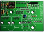
- □ U2 - 14 pin socket. The socket has a notch on one end and the notch must be installed to match the direction on the silkscreen.

The Notch faces right.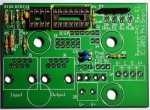
- □ U1 - 8 pin socket. The socket has a notch on one end and the notch must be installed to match the direction on the silkscreen.
- □ Install LEDs
- □ D3,D4 - Yellow LED. LEDs are polarized and they have to be installed with the correct orientation. The anode side of the LED with the longer leg goes in the top round hole.
- □ D5,D6 - Green LED. LEDs are polarized and they have to be installed with the correct orientation. The anode side of the LED with the longer leg goes in the top round hole.
- □ D3,D4 - Yellow LED. LEDs are polarized and they have to be installed with the correct orientation. The anode side of the LED with the longer leg goes in the top round hole.
- □ Install Headers. The short end of the header is soldered into the PCB.
- □ J4 - 2 pin header.
- □ J1, J7 - 3 pin header.
- □ J2 - 6 pin header.
- □ J3 - 2x5 (10) pin header.
- □ J4 - 2 pin header.
- □ Install Voltage Regulator
- □ IC3 - LP2950CZ-5.0/NOPB voltage regulator. The voltage regulator is polarized and it has to be installed with the correct orientation. Install in location U3 with the flatside of the regulator facing the top of the board and matching the orientation on the silkscreen.
- □ IC3 - LP2950CZ-5.0/NOPB voltage regulator. The voltage regulator is polarized and it has to be installed with the correct orientation. Install in location U3 with the flatside of the regulator facing the top of the board and matching the orientation on the silkscreen.
- □ Install Fuse Holder
- □ Fuse holder.
- □ Fuse holder.
- □ Install Connectors
- □ J8 - 2 pin screw terminal. Install so the wire opening faces off the edge of the board.
- □ J9 - 4 pin euro style header. This connector is polarized.

The euro style connector is installed with the slotted side to the top.
- □ J8 - 2 pin screw terminal. Install so the wire opening faces off the edge of the board.
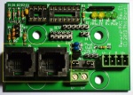
- □ Install RJ45 Jacks
- □ J5,J6 - RJ45 Jack. The jacks are polarized and they have to be installed with the correct orientation. Gently install all 8 pins into the holes and them firmly press down on the socket to seat the plastic pins in the holes in the PCB.
- □ J5,J6 - RJ45 Jack. The jacks are polarized and they have to be installed with the correct orientation. Gently install all 8 pins into the holes and them firmly press down on the socket to seat the plastic pins in the holes in the PCB.
- □ Install Fuse
- □ Install 5A fuse.
- □ Install 5A fuse.
- □ Install ICs
- □ IC1 - SN65LBC179PE4, RS485 line chip. The IC is polarized and it has to be installed with the correct orientation.

The IC has a notch on one end and the notch must be installed to match the direction on the silkscreen.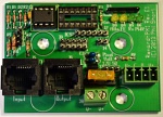
- □ IC2 - PIC16F1825-I/P PIC microprocessor. The IC is polarized and it has to be installed with the correct orientation.

The IC has a notch on one end and the notch must be installed to match the direction on the silkscreen.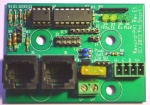
- □ IC1 - SN65LBC179PE4, RS485 line chip. The IC is polarized and it has to be installed with the correct orientation.


Configure Jumpers
You must place the appropriate jumpers on the various headers to configure the Renard PX1 Pixel Controller.
J1- DMX Termination Resistor / RS232 Input

Install a shunt (jumper) across Pin 1 and Pin2 if you are using RS232 Input to the controller. Install a jumper across Pins 2 and Pin 3 if you are using regular RS485 input.
J3- 2x5 Options Connector
This connector is used to set various special options. The default is no jumpers used on this header.
If and only if you are using WS2801 pixels and have issues with stray flashing on older pixels, you can put a single jumper on the two most left pins of the header (up and down) and restart the PX1. This option uses a slightly different timing that will only work with WS2801 pixels. Generally most WS2801 pixels will not need this jumper.
J4- Inline Settings Programming
Do not install any jumper here until instructed to do so. This jumper is only used to change the settings in a PX1 by using a specially formatted vixen or other control software data stream. See Configuring the Settings via a Renard Data Stream
J7- Voltage Selector

This 3 pin jumper is used to select the power source of the control circuit on the board. This jumper must be set to match the voltage requirements of your pixels. If the power input to the board is 12VDC, then jumper must be placed on the two left pins. If the power input to the board is 5VDC, then the jumper must be placed on the right two pins.
IT IS CRITICAL THAT YOU CONNECT THE CORRECT VOLTAGE TO THE UNIT AND HAVE THE CORRECT VOLTAGE INPUT SETTINGS! YOU MAY DAMAGE THE CONTROLLER AND PIXELS IF YOU CONNECT THE WRONG VOLTAGE OR HAVE THE WRONG VOLTAGE SETTINGS ON J7!
Program PIC
You must configure the firmware to match your system settings and then build the firmware (create a .hex file) as outlined below.
The PX1 Pixel Controller has a built in ICSP programming header that you can connect directly to a PICKIT 2 or PICKIT3 programmer and program the firmware into the PIC without removing the PIC from the PCB. Pin 1 of the ICSP header is on the right side of the 6 pin header. After building the .hex file in MPLAB you must then download the firmware into the PIC using either the PICKIT 2 or MPLAB IDE software. Remove the external power from the PX1 and use the power from the Pickit2 to program the PIC. Disconnect the Pixels from the controller while you are programming the PIC. Once you have successfully download the firmware into the PIC the controller is ready to be tested.
- Do not install any shunt in J4 while programming the PIC.
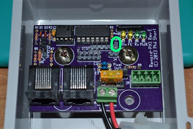
J2-ICSP Programming Header
J2 is the 6 pin header located in the top center of the board that allows In Circuit Serial Programming. J2 allows the PIC microprocessor to be programmed in place on the board by directly connecting a PICKIT2 or PICKIT3 programer. It eliminates the need to remove the PIC from the PCB to program or modify the programming in the PIC.
Pin 1 is the square hole towards the right side of the board closest to the mounting hole.
| J2 ICSP Pin Assignments | ||
| Pin # | ||
| Signal | ||
|---|---|---|
| 1 | VPP/MCLR | |
| 2 | VDD Target | |
| 3 | VSS (Ground) | |
| 4 | ICSPDAT/PGD | |
| 5 | ICSPCLK/PGC | |
| 6 | N/C | |
Congratulations, you have finished constructing your Renard PX1 Pixel Controller.
Connections
After you have finished building the PX1 Pixel controller you need to make the appropriate connections to power the board, connect the pixels and supply data to and from the Renard network that you are connecting the controller to. The connectors on the PCB are as follows:
J5 and J6-Renard Input and Output
The two RJ45 Connectors J5&J6 near the bottom left of the board are used to bring data signals to and from the board. J5 on the left side is the signal input from the PC or previous Renard controller. J6 on the right side is the output to be daisy-chained to the next Renard controller. These connections are the standard Renard daisy chain configurations. The pins on these connectors are used as follows:
| Serial Data Connector Pin Assignments | ||
| Pin # | RJ45 Connector | |
| J5 Input | J6 Output | |
|---|---|---|
| 1,2 | GND | GND |
| 3 | NC | NC |
| 4 | Data- (Rx) | Data- (Tx) |
| 5 | Data+ (Rx) | Data+ (Tx) |
| 6,7,8 | NC | NC |
J8-Pixel Power Input
J8 is the 2 pin terminal block located at the bottom center of the PCB. The Renard PX1 can be powered by either 5 or 12VDC (depending on pixel type). If you are using 5VDC, you can omit the voltage regulator and set Jumper J7 to the two right pins (5v position).If you are using 12VDC, then you must use the on board voltage regulator and set Jumper J7 to the two left pins (12v position). IT IS CRITICAL THAT YOU CONNECT THE CORRECT VOLTAGE TO THE UNIT AND HAVE THE CORRECT VOLTAGE INPUT SETTINGS! YOU MAY DAMAGE THE CONTROLLER AND PIXELS IF YOU CONNECT THE WRONG VOLTAGE OR HAVE THE WRONG VOLTAGE SETTINGS ON J7!
| J8 Power Input | ||
| Pin # | ||
| Voltage | ||
|---|---|---|
| 1 (square pad on left) | GND (V-) | |
| 2 (round pad on right) | V+ | |
J9 - Output to Pixels
![]() J9 is located along the bottom right side of the board and is a 4 pin Euro style plugable connector used to connect to the Pixels. Pin 1 of the connector is on the left side and is marked by the square hole on the silkscreen. You must wire the plug onto your pixel string according to the correct wire color code for your pixels. Please check with your vendor to confirm the color code of the various wires and how to determine the input end of your pixel string. Some examples of the various wiring color codes can be found here. Another common choice is to wire a waterproof connector to the euro plug and use waterproof connections to their pixels. Note that WS2811 pixels only have 3 wires( V+, Data, GND) and they do not require a Clock wire.
J9 is located along the bottom right side of the board and is a 4 pin Euro style plugable connector used to connect to the Pixels. Pin 1 of the connector is on the left side and is marked by the square hole on the silkscreen. You must wire the plug onto your pixel string according to the correct wire color code for your pixels. Please check with your vendor to confirm the color code of the various wires and how to determine the input end of your pixel string. Some examples of the various wiring color codes can be found here. Another common choice is to wire a waterproof connector to the euro plug and use waterproof connections to their pixels. Note that WS2811 pixels only have 3 wires( V+, Data, GND) and they do not require a Clock wire.
| J9 Pixel Output Pin Assignments | ||
| Pin # | ||
| Signal | ||
|---|---|---|
| 1 | GND (V-) | |
| 2 | Clock (C) | |
| 3 | Data (D) | |
| 4 | V+ | |
Indicator LEDs
Attn
ON (flashing) when J4 jumper for Renard Data Stream Configuration is in place.
Rx
This LED flashes as it is receiving data from the input connector.
FE
This LED flashes if there is a framing error in the incoming data stream. This is likely due to the PIC or the PC output signal using different baud rates.
Pwr
This LED lights if there is power supplied to the board.
Firmware
The firmware for the Renard PX1 Pixel Controller needs to be optimized and configured for your specific use. There are several parameters that can be set in the firmware including:
- Baud Rate: Allows you to set the controller to match the speed of your existing Renard network. The default is 115200.
- Number of Pixel Groups: Allows you to set the specific number of pixels to be attached to controller (1-200)
- Renard Start Address: This uses the standard Renard protocol of defaulting to Channel 1, but can be set to higher channels in multiples of 8.
- RGB Order: Allows to make corrections for strings where the pixels respond in a different color order
- Grouping: Allows you to treat multiple pixel as one pixel, cutting down on the number of channels used.
These configuration parameters can be changed in the assembly file (see below), which causes these values to be stored in the EEPROM on the PIC. These parameters can be changed later on by installing a shunt in J4 and sending a specially crafted sequence from Vixen or other similar software.
The firmware is available in an assembly file (.asm) file that needs to be compiled and built with Microchip's free MPLAB IDE software or MPLAB X IDE.
If you have never compiled firmware before, there is an excellent series of tutorials available here.
Older versions of MPLAB IDE may not support the 16F1825 PIC and you my need to update the MPLAB IDE to a later version. You may also have to update the PICKIT2 software to support the 16F1825. Version 2.61 supports the 16F1825 PIC and allows you to program the firmware into the PIC. While you are updating the PICKIT 2 software, you might want to also download the latest device file Version 1.62.14 and replace the file in the PICKIT 2 program directory with this file.
For a step by step guide to program the pic for a PX1 using the Pickit Click here.
One note: When compiling the firmware you must choose Relocatable code as the compile option.
The firmware file can be found here.
Configuring the Settings via the Firmware
Before you build the code using MPLAB, you can set the variables associated with the controller and how you plan to use it in the .asm file. By adjusting the parameters and then building the code with those parameters, you result in a .hex file specific for your project. The parameters that can be set are:
- Baud Rate:
- Find the line in the code that says " #define BAUDRATE_INDEX_DEFAULT BAUDRATE_115200" and adjust the baudrate to one of the following values:
- 19200, 38400, 57600, 76800, 115200, 230400, 460800
- Find the line in the code that says " #define BAUDRATE_INDEX_DEFAULT BAUDRATE_115200" and adjust the baudrate to one of the following values:
- Number of Pixel Groups:
- Find the line in the code the says " #DEFINE GROUP_COUNT 50" and adjust it from 1 -200
- Renard Start Address:
- Find the line in the code that says "#define Renard_START_ADDRESS 1" and set it your start channel.
- RGB Order:
- Find the line in the code that says "#DEFINE DEFAULT_RGB_ORDER_CODE RGB" and set it to one of the following values:
- RGB, RBG, GRB, GBR, BRG, BGR
- Find the line in the code that says "#DEFINE DEFAULT_RGB_ORDER_CODE RGB" and set it to one of the following values:
- Grouping:
- Find the line in the code that says " #DEFINE GROUP_SIZE 1" and change it you the number of pixels you want in a group. The default is 1.
Configuring the Settings via a Renard Data Stream
The PX1 can be configured inline by using a specially formatted Renard Data stream. The basic process using Vixen is as follows:
- Choose your start address
- Create a vixen sequence with 6 channels and make it just 1 time period long
- Then you need to enter the start address into the two channels by using the intensity value feature of vixen set the values from 0-255 (Not 0-100%)
- Enter into Channel 1 the Start Address MSB as found in the table below.
- Enter into Channel 2 the Start Address LSB as found in the table below.
- Example:
- If start address = 1
- Channel 1 = 0
- Channel 2 = 1
- If start address = 45
- Channel 1 = “0”
- Channel 2 = “45”
- If start address = 257
- Channel 1 = 1
- Channel 2 = 1
- If start address = 1
- Enter into Channel 3 the Baudrate code as found in the table below.
- Enter into Channel 4 the Group Size, the number of pixels you want to cluster into a group.
- Enter into Channel 5 the Group Count, the number of pixels directly connected to the controller from 1-200.
- Enter into channel 6 the rgb_order_code as found in the table below.
- Power off the PX1, install the jumper J4 on the PX1 then power ON the PX1 (the ATTN LED should be blinking) and set up Vixen to send out the Renard data packets with the new address or configuration change.
- Run the sequence. When the controller has accepted the new address and stored in the EEPROM, the ATTN, RX and FE LEDs will come on and stay on solid.
- Power off the PX1 and remove the jumper J4 then power ON the PX1. The changes are now in effect.
NOTE: You must have a value in each channel even if you do not wish it to change
Example - If you only want to change the RGB order, you must set the default values in the other packet channels.
PX1 Programming Packet Format
| Inline PX1 Programming Settings | ||
| Packet (Channel) | ||
| Value | Default | |
|---|---|---|
| 1 | Start Address (MSB) | 0 |
| 2 | Start Address (LSB) | 1 |
| 3 | Baudrate Code | 4 |
| 4 | Group Size | 1 |
| 5 | Group Count | 50 |
| 6 | RGB Order Code | 0 |
Start Address Packet Format
| Inline PX1 Programming Settings | ||||||
| Start Address | Packet 1 MSB (Channel 1) |
Packet 2 LSB (Channel 2) | ||||
|---|---|---|---|---|---|---|
| 1-255 | 0 | Actual Start Address | ||||
| 256-511 | 1 | Start Address - 256 | ||||
| 512-767 | 2 | Start Address - 512 | ||||
| 768- 1023 | 3 | Start Address - 768 | ||||
| 1024-1279 | 4 | Start Address - 1024 | ||||
Baud Rate Packet Format
| Inline PX1 Programming Settings | ||
| Baud Rate | ||
| Baud Rate Code Packet 3 (Channel 3) | ||
|---|---|---|
| 19200 | 0 | |
| 38400 | 1 | |
| 57600 | 2 | |
| 76800 | 3 | |
| 115200 | 4 (Default) | |
| 230400 | 5 | |
| 460800 | 6 | |
Color Packet Format
| Inline PX1 Programming Settings | ||
| Color Order | ||
| RGB Code Packet 6 (Channel 6) | ||
|---|---|---|
| RGB | 0 (Default) | |
| RBG | 1 | |
| GRB | 2 | |
| GBR | 3 | |
| BRG | 4 | |
| BGR | 5 | |
.
.
.
Configuring the Settings via the PX1 Setup Application
DIYC member "bolwire" created a small application which assists in setting up a PX1 pixel controller. This takes the place of using a vixen sequence to configure the PX1, as outlined above.
The information entered into the app, should be as directed above. The only difference is that you do not need to enter the MSB bit, this is determined by the application.
After entering your setup details, simply connect your PX1 and click *Write Data*, you will get a confirmation if the data was sent successfully, but as before, the LEDs on the PX1 should behave as according to the wiki as and indication as to the data being accepted and saved.

Download the application here
The initial thread is here.
Enclosure
The Renard PX1 pixel controller can be mounted in the users choice of enclosures. One common choice is the TA-200 enclosure.

The PX1 has three screw holes that line up perfectly with the plastic standoffs in the inside of the TA-200 enclosure.
Other Information
Renard PX1 Pixel Controller Discussion Threads
Initial Thread
Beta Test Thread
Group Buy Interest Thread
Video
TBD
FAQ
- Question: I have never used pixels before,how can I learn more about where to begin and how to use pixels and the Renard PX1 Pixel Controller?
- Answer: Read The Pixel Newbie for step by step information about setting up your first pixels.
- Answer: Read The Pixel Newbie for step by step information about setting up your first pixels.
Related Links
Different Styles of Pixels
Controllers
Dumb RGB or Intelligent Pixels??
Things You Will Need To Get Started With Pixels
Pixel Wiring Colors
Power Supplies
Pixel Connectors
Power Injection
Waterproofing Pixels