In this post, I will show how to wire a SSR box using one indoor extension cord and a wirenut. This method using the daisey chain option will save a lot of money on extension cords in your setup.
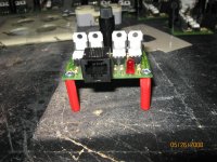
I am using a wall mount electrical box, but this method can be applied to any enclosure you choose. You can use any length cord you wish... 6', 9', 12', or 15'. I highly recommend to use at least a 9' cord though, as very rarely will all the relay boxes be within 4' of each other.
OK, lets get started.........
First, lets cut the cord to the the specs below.

Now, the two 6" sections seperate them into seperate wires so you have four 6" wires. Strip one end 1/4" and the other end 3/4".
Take the two cord ends and seperate them 6". You will notice that one wire is smooth and one is ribbed, cut the smooth wire at 5" on both cords. Strip one of the 5" wires you now have on both ends 3/4", and the other 5" wire will get 1/4" and 3/4" (do not tin the 3/4" end of this wire!). You can tin the wires if you wish. I also make a 'hook' on the wires for the screws and tin those. You can also use crimp on terminals if you wish. Which ever way you go, just make sure no stray strands of wire are hanging out to short something out.
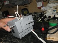
This is what you should have......

Now insert the wires into your enclosure. Take the 5" wire with the 1/4" stripped end and group it with the two shorter (smooth wires) wires of the two cords, twist together and secure using a wire nut.
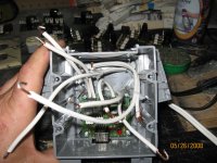
The other 5" wire (with 3/4" strip on each end) is used to connect the common (silver screws) on the two outlets. Now secure the two longer ends of the two cords to the two remaining silver screws of the outlets. The other four 6" wires are for the channel connections from the SSR pcb.
You also need a way to keep from the wires being pulled out of the enclosure. In my setup I use two zip ties on the cords.


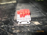
The outlets will have two small tabs on them that must be removed before assembly. Remove the tabs from the side of the gold screws. This separtes the outlets so we can have 4 channels.

Now attach the 4 channel wires from the pcb to the outlet's gold screws. Make sure that you always attach the wires in the same configuration on all of your boxes. This way, when testing, you know if you have a wire going to the wrong outlet. A good order is...
1 3
2 4

Push everything into the box, making sure to not have the wires laying on the triacs or the heatsink (if used). Look everthing over, look over it again, one more time... if all looks good put your cover on and test.")
You can now plug relays to each other in the yard and save a bunch on cords. The reason for the length on the female plug is, I wrap it around to the side of the box and zip tie it. This allows it to be covered with the bag I use to cover my boxes to keep them weather proof.

IMPORTANT!!!!
Do not exceed the amperage rating of the cord on the first relay box of the chain. The amps can add up fast when you chain them together. Know what this rating is for the cords you are using.
I am using a wall mount electrical box, but this method can be applied to any enclosure you choose. You can use any length cord you wish... 6', 9', 12', or 15'. I highly recommend to use at least a 9' cord though, as very rarely will all the relay boxes be within 4' of each other.
OK, lets get started.........
First, lets cut the cord to the the specs below.

Now, the two 6" sections seperate them into seperate wires so you have four 6" wires. Strip one end 1/4" and the other end 3/4".
Take the two cord ends and seperate them 6". You will notice that one wire is smooth and one is ribbed, cut the smooth wire at 5" on both cords. Strip one of the 5" wires you now have on both ends 3/4", and the other 5" wire will get 1/4" and 3/4" (do not tin the 3/4" end of this wire!). You can tin the wires if you wish. I also make a 'hook' on the wires for the screws and tin those. You can also use crimp on terminals if you wish. Which ever way you go, just make sure no stray strands of wire are hanging out to short something out.
This is what you should have......

Now insert the wires into your enclosure. Take the 5" wire with the 1/4" stripped end and group it with the two shorter (smooth wires) wires of the two cords, twist together and secure using a wire nut.
The other 5" wire (with 3/4" strip on each end) is used to connect the common (silver screws) on the two outlets. Now secure the two longer ends of the two cords to the two remaining silver screws of the outlets. The other four 6" wires are for the channel connections from the SSR pcb.
You also need a way to keep from the wires being pulled out of the enclosure. In my setup I use two zip ties on the cords.


The outlets will have two small tabs on them that must be removed before assembly. Remove the tabs from the side of the gold screws. This separtes the outlets so we can have 4 channels.

Now attach the 4 channel wires from the pcb to the outlet's gold screws. Make sure that you always attach the wires in the same configuration on all of your boxes. This way, when testing, you know if you have a wire going to the wrong outlet. A good order is...
1 3
2 4
Push everything into the box, making sure to not have the wires laying on the triacs or the heatsink (if used). Look everthing over, look over it again, one more time... if all looks good put your cover on and test.
You can now plug relays to each other in the yard and save a bunch on cords. The reason for the length on the female plug is, I wrap it around to the side of the box and zip tie it. This allows it to be covered with the bag I use to cover my boxes to keep them weather proof.

IMPORTANT!!!!
Do not exceed the amperage rating of the cord on the first relay box of the chain. The amps can add up fast when you chain them together. Know what this rating is for the cords you are using.
Last edited: