I'm baaaaaack.
I wanted to come back with a little info. I don't know if I'll go this route, but I is my current plan. I call it the CandyCam (yeah, a dumb play on the work Candy Cane).
It is a webcam out of an old laptop, if you dig around eBay, there are LOTS out there. If you are to go this route, get one with the cable still attached, they cost a few dollars more usually, but the connectors are REALLY small and make soldering and probing a pain. The first one I bought didn't have any cables or even probe points, so it was a pain in the butt and seemed to die a slow death from me soldering and re-soldering, and making poor assumptions on pinouts. Some of the webcams also have a mic, but I didn't pay attention to that.
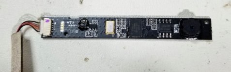
The webcam I am currently using is out of a Samsung NP-R730 laptop. It is part number BA59-02690A (that is the camera all the way on the right in the black circle).
From experience now, I can tell you that there is no rhyme or reason for the pinout or color coding. For me, the fact that this unit had test probes AND a cable, is what made me choose it.

Looking at the above image, you can see my probing the test points a bunch. The easiest thing for me to do was find the ground point. Set up your multi-meter for continuity mode, pick a probe point (or a wire on your cable if you don't have a probe point), and drag your other probe across different places on the board. The ground is going to show up all over the place: the crystal's case, as a ground point for the ICs, some of the caps, grounded mount points if your board has them (mine does not). Once you figure out ground, mark it down. Next, you want to find your 5V VCC point, this is a little trickier. You would think that you could do the same thing for VCC and the ICs, but a lot of the boards have an LDO or voltage regulator that drops the voltage, so that isn't always simple. Try to find an IC up front and probe it out. When that is done, all that should leave is the two data pins for the USB. The data pins were pretty simple since I had a cable, that's because the wires are usually a twisted pair. Another way to figure it out is to probe that conformal coated part just to the right of the "94V-0" silkscreen. I think that is a SMD TVS Diode for ESD protection (both I played with had them). For this particular board, VCC was on the black wire at the top (yeah makes perfect sense.....), Ground is orange, and the two data lines were brown and red. I didn't know which was D+/D-, so you have a 50% chance of getting it right on the first try. If you don't make a connection when you connect it to a PC, swap those two. Below you can see the connection from the PCB's cable to the cable of my micro USB cable (I'll explain why micro USB in a minute).

The simplest thing at this point is to plug it into you PC. If you are lucky your PC will recognize a webcam. If you are kind of luck, it will recognize a USB device, but you will need a driver for it. If you are really unlucky, you will have backwards data lines (which you will need to swap), or you did something wrong. I find Linux recognizes webcams automagically way more often than Windows. I didn't want to risk screwing up my USB port on my laptop (if I REALLY screwed something up, so I plugged it a USB Zero W I had lying around (hence the micro USB plug need mentioned above). Success, it saw it immediately!
After doing some researching an weighing some options, I decided to blow away my Pi's SD card and install the
MotionEye OS on it. This is a pretty sweet OS designed to run on all sorts of systems (make sure you grab the right release build for the hardware you are putting it on), that is a GUI front-end for the
Motion webcam project (a lot of this stuff is popular with the DIY security system crowd). It allows for motion detection, timelapse videos, live views, guest live views, etc. Very neat. I've had it running in my workshop for about a week now and it seems pretty seamless. I don't know how long I'll keep it up, and I don't have it pointed on me, but I do work from home, so the lights are on during work hours usually. I'll keep it up for a week and then delete this part from the post.
Hope this is helpful. Like I said, I am not sure I will go this route, but I thought it was pretty neat. The streaming is pretty clear (good enough for a ~7 year old webcam), responsive, and the admin login has TONS of settings and better quality that the user mode. I am not sure how well this will work in the cold of winter (I suppose I should put this outside since it is still winter.....), but it was pretty chearp. I think I am going to slide it into one of those M&M candy cane looking containers and putting it into the corner of my dispenser (so it will out of the elements, have power present, and I can hide the Pi in the sidewall where I keep the rest of the electronics for the prop anyway.
The live view is
here.