FireWorks 2011 the MiniRose

jrock64

New member
New year new project, smaller scaled down version, but more control.
Building two of these to add to this years show.

Just 4.5 ft across and 32in high but a lot more color possibilities.
Only 6 branches with 3 spokes each, for 18 spokes total.

12M of 60led/M RGB strip cut into 4 segment, 8in strips.
3 strips per spoke = 9 channels per spoke * 3 spokes = 27 channels per branch
Just happens to be the amount controlled by the 27 channel RaWu DMX controller

Will have individual control of all the elements on one branch, all branches will be identical
This will allow center out, or top down effects, but not side to side.

Just a matter of if I have enough time to finish them.

Joel
 
Faced with the prospect of having to build 2 more hubs, I thought there has to be an easier way.
Last year I eyeballed the flanges into what I thought was the correct location, evenly spaced, and square, then tried to clamp them long enough to get some weld on them.

With age comes wisdom.

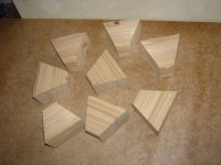
Grab a scrap of 2x4, set your miter saw at 22.5 degrees and cut, flip the piece and cut again, repeat 7 more times.
attachment.php

MiniRose2011_Wood Wedges.JPG

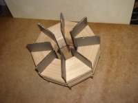
Form those wedges into a ring, and secure with rubber bands.
attachment.php

MiniRose2011_Wood Ring.JPG


Slip your flanges into the slots
attachment.php

MiniRose2011_Wood Steele.JPG

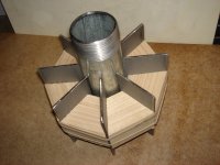
Slip the pipe into the hole and center the wedges on the flanges.
attachment.php

MiniRose2011_Wood Pipe.JPG

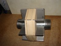
Snug everything up and you are ready to weld, no clamping, and so much easier to set up.
I may wrap it with masking tape to give additional strength and to protect the rubber bands from the sparks.
attachment.php

MiniRose2011_Wood Weld.JPG

Joel
 
Last edited:
Joel, does this involve pyrotechnics of any kind? If so, that is prohibited from being discussed here.
 
Sorry Wayne, only blinkey flashey 5050 LEDs
Not designed to release any sparks or magic smoke.

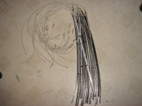
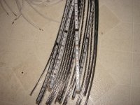
Have most of the LEDs prepped into 9 channel 24in long strips.
That whole stack goes on one MiniRose
attachment.php

MiniRose2011_5050 stick.JPG

A better close up of one strip
attachment.php

MiniRose2011_5050 close.JPG

Joel
 
Last edited:
Jeez, ya going to make us green with envy again.

Have most of the LEDs prepped into 9 channel 24in long strips.

Can you give us so close up details on the LED strips?


My eldest son starts his welding course this month, ( means I get to buy a new Mig welder) so he may be charged with a similar project.
 
All the detail is hidden on the back.
I was looking for some kind of backing in the Plexiglas section at Menards.
I found what they called a desk topper made out of PVC,
Black in color, probably recycled plastic.
The sheet was 2 x 3 feet and about .10 in thick.
I ripped it into 1/2 in strips to match the 5050 strip width.

The strip was 5050 RGB 60 LEDs/m for maximum intensity.
I cut it into 4 segment sections that are 8in long and 12 LEDs each. That's bright.

9 channels takes 10 conductors, so I used 2 telephone wires.
The first 4 conductor provides the common positive and the first set of RGB channels.
A second 6 wire conductor provides the other 2 sets of RGB channels.
I used a 1/32 drill to allow the stripped wires to pass from the back to the front.
Once it is all soldered up and tested, two pieces of PVC heat shrink seal it up.
The first 1/2 in and the second 3/4in and a little hot melt seal it up and it should be weatherproof.

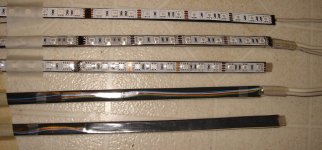
1 In progress needs second wire and heatshrink
2 Completed front power end
3 Completed front tail end, you can see the hotmelt plug in the end
4 Completed back power end
5 Completed back tail end.
attachment.php

MiniRose2011_5050 zoom5.JPG

I got my heat shrink here http://www.buyheatshrink.com/heatshrinktubing/pvc-heat-shrink-tubing.htm
PVC waterclear and UV stable

JOel
 
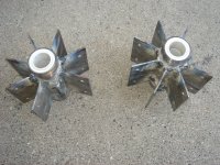
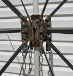
Two new hubs all welded up and ready to go.
It ain't pretty, but it will hold.
attachment.php


MiniRose2011_Welded hubs.JPG

Tomorrow I get to start the fun project, stay tuned.

Joel
 
Finally got some more welding done.

Only 18 spokes from straight on.
attachment.php

MiniRose2011_Welded branches1.JPG

From a lower angle you would actually see it from.
attachment.php

MiniRose2011_Welded branches2.JPG

Close up of the attachment.
attachment.php

MiniRose2011_Welded branches close.JPG

This year the anchor cables just bolt to the bottom of the branches.

Joel #424
 
Last edited:
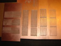
Finally got the etch a sketch working.
Ok my CNC mill I have sometimes mentioned.
Took a few tries, but you are only beaten if you stop trying.

Progress from left to right
first sheet the horizontal ones, 90 and 45 degree bits, not good.
Second sheet, two vertical sets, 60 degree bit, lots of burrs
Third sheet, one set, 20 degree bit, some burs but salvageable with a razor blade
Last sheet one vertical set, a new 20 degree bit...SWEET no burrs and no clean up
MiniRose2011_MRB1.JPG
attachment.php


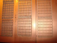
Close up of the last 3 you can see all the burs on the first one.
The second one was done with a 20 degree tip, turns out about 1/64 was broke off the end.
Last one tried a new bit. No burrs, and next to no cleanup.
The holes are #64 .0360" .90mm
I checked the trace size with my carbide drills as a gauge and I would say those lines are only #80 .0135" or .35mm. Thats SOIC size
Both of the last two boards were done with the same milling program, thats how much difference a broken bit makes.
MiniRose2011_MRB2.JPG
attachment.php


And here is what they are going to be used for.
Blocks to plug all those LEDs into, a simple project, but you have to start somewhere.
MiniRose2011_MRB3.JPG
attachment.php


JOel 527
 
Last edited:
Looking good. I just purchased some different size bits - got some 20, 45 and 60, I think.

A little sandpaper should get rid of the burrs, don't you think?

What are you using to generate your g-code for the CNC? And did you start with a specific PCB layout SW?

I've got a small desktop CNC machine that I'm playing with for small wood work, but plan to do some PCB board stuff soon...
 
I loved the welding jig. I still have to learn that spending time making jigs for stuff is the SAME as spending time making stuff! :)
 
I find that quite often I spend an hour or two making a jig so I can save 10 minutes. I feel so much better knowing I did it right. :rolleyes:

Yes that was sarcastic but true. :smile:
 
When I mill circuit boards, I typically only use a 60° bit and route progressively, increasing the separation by half the bit width.

Your third attempt looks like what I had been getting for the last six months. I thought I had gotten a bunch of bits that weren’t sharpened correctly. Then one day I just happened to be watching as the spindle stopped from its 30,000 RPM rotation speed. It works much better, now that it’s turning the correct direction. :-D
 
Looking good. I just purchased some different size bits - got some 20, 45 and 60, I think.
what ever works for you. I was about to go to mill ends if I had not got it to work.

A little sandpaper should get rid of the burrs, don't you think?
not even close. took the new edge on one of those snap blades to cut 2oz copper

What are you using to generate your g-code for the CNC? And did you start with a specific PCB layout SW?
I am using Eagle free version, limited to 3" by 4"
Using the gcode plug in to create the cnc files.
running those thru opti to clean up the tool paths.
Transferring that to a bootable memory stick that runs turbocnc

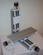
I've got a small desktop CNC machine that I'm playing with for small wood work, but plan to do some PCB board stuff soon...
Looks like the site is mostly down, but here is a pretty good picture of what mine looks like
main.jpg

I loved the welding jig. I still have to learn that spending time making jigs for stuff is the SAME as spending time making stuff

I find that quite often I spend an hour or two making a jig so I can save 10 minutes. I feel so much better knowing I did it right. :rolleyes:
It may take longer to make the jig, but at least you feel productive while making the jig.
If I had tried to clamp the parts in place I would have just been frustrated.
When you deed to drill 50 holes and they all need to be within 1/16 of an inch a center punch just is not accurate enough

When I mill circuit boards, I typically only use a 60° bit and route progressively, increasing the separation by half the bit width.
I tried, but the tool path was too wide for me. I wanted to see what the smallest path I could achieve was.

Your third attempt looks like what I had been getting for the last six months. I thought I had gotten a bunch of bits that weren’t sharpened correctly. Then one day I just happened to be watching as the spindle stopped from its 30,000 RPM rotation speed. It works much better, now that it’s turning the correct direction. :D
I don't think there is a backwards to a D bit.
But if I could run my bits backwards. I could use both edges and get twice the life out of them.:D

Joel 628

If the mods want to start a new milling forum, they can move these posts there
 
Ernie and Joel,
What kind of spindle are you using? I have both a Dremel and a Bosch Colt router that I started with. Some folks on other forums mentioned a special spindle just for PCB work...not sure I'm ready to make that investment...
 
1 blooming rose, and 2 mini roses.

[video=vimeo;25949090]http://vimeo.com/25949090[/video]
JOel
 

Attachments

  • MiniRose2011_July41.JPG
    MiniRose2011_July41.JPG
    42.3 KB · Views: 45
  • MiniRose2011_July42.JPG
    MiniRose2011_July42.JPG
    48.7 KB · Views: 63
Last edited:
Back
Top