Barnabybear
Active member
Hi all, hope you’ve had a good Christmas and wish you all health and happiness for the new year.
This on the face of it is the most useless hack of the year, but it’s a proof of concept that could be quite useful to some people. It combines work from ‘ukewarrior’ (RGB LED hack) and ‘sporadic’ (software).
Someone gave me a colour changing light bulb (with IR remote) for Christmas and said “I bet you can do something with that” http://www.ecolight.pl/media/wysiwyg/E27.pdf the last one.
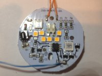
So in true DIYC style I fitted in a lamp, played with the remote for 2 minutes and headed for the internet. It appears that there are various hacks for them most using Arduinos to send or simulate the IR commands that are limited to 16 different colour / levels. Something more drastic was called for, out with the knife and off with the top.

Back to the internet to find out what was on the board, the important bits:
A HT68F002 http://img.ozdisan.com/ETicaret_Dosya\455462_2776624.pdf
And some Si2302DS http://www.vishay.com/docs/70628/70628.pdf
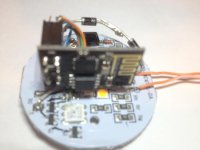
We have something to play with and its 5v. I’m sure that if I could have been bothered to read the 177 pages and done some research on the HT68F002 I could have done something cool with it. But I couldn’t be bothered, so out with the knife cut the legs off and de-solder the feet. Solder some cat5 onto GND and the 3 output pads to the FETs (R,G and B) and into my parts box for a ESP8266-01 (you might have guessed from my posts I like these), 2 off 10K SMT resistors and 2 off 1n4005s (bought a lot others will work).
Rebuilding:
The ESP8266 is a 3.3V device but is quite tolerant, so I put the two diodes together from the 5V supply on the board to the ESP Vcc, given that the diodes will each drop 0.7V that should give me 3.6V at the ESP.
Ground from the ESP to Ground on the board.
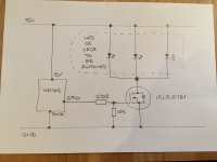
GPIO 0 on the ESP to the Red FET on the board. Also GPIO 0 on the ESP to Vcc via a 10k resistor.
GPIO 2 on the ESP to the Green FET on the board. Also GPIO 2 on the ESP to Vcc via a 10k resistor.
GPIO 3 on the ESP to the Blue FET on the board.
Now I hear some of you shout – The ESP8266-01 only has 2 GPIOs 0 & 2. That’s sort of correct it only has 2 labelled as GPIOs, Tx and Rx are also GPIOs (1 & 3 respectively) you have to change them from their boot configuration using ‘pinMode(<PIN>, FUNCTION_<FUNCTION>);’ all the functions can be found here http://www.esp8266.com/wiki/doku.php?id=esp8266_gpio_pin_allocations
Anyway we need ‘pinMode(3, FUNCTION_3);’ to set Rx as a GPIO. I chose to sacrifice Rx so that I could still have Tx available for a serial connection to find out the IP address acquired and to debug. That sorted, what happens if we want to re-flash the ESP? In flash mode all pins are returned to their boot state, so Rx will still be Rx, plus you can now OTA update.
We need some code:
This is based on ‘sporadic’ ESP8266_Test.ino https://github.com/forkineye/E131/blob/master/examples/ESP8266_Test/ESP8266_Test.ino
To get any sort of decent control we are going to need 3 channels of PWM that can respond to 0 to 255 as commands. Fortunately the ESP is capable of PWM, the down side is that its rubbish at it. Every time you change the PWM ratio you have to stop and restart the output for it to take effect, with one exception – ‘analogWrite(<output>, <value>)'. The ESP doesn’t have a digital to analog converter, it uses a high frequency square wave output and relies on circuit capacitance to convert this to an analog signal. As this is PWM there is no reason why it shouldn't work with FETs and LEDs particularly as the parameters for an analogWrite with the ESP are 0 to 255 (don’t you just love this ?).
Finally to the sketch:

The end result, 256 dimmable on all 3 colours, full mixing and WiFi controlable, with one down side, on power up the one colour of the device lights up untill a WiFi connection is found. It's a coding issue that is simple to sort (WiFi connection is called before the outputs are declared and set to 0), but was quite usefull for testing as when the bulb went dark I knew it had connected. It might even be a feature, for the first 2 mins at power up, Yellow connecting, Green connected and Red failed to connect. You could power up your display and watch the colour cycle through to all green before all going off.
I said at the start, this was only a proof of concept but is working really well and has demonstrated:
You can use more than two GPIOs, in practice 3, theory 4.
analogWrite works as PWM, they go off at Zero and everything.
On this unit the FETs seemed happy with the voltage and frequency supplied by the ESP.
In theory other dumb RGB strip, DC SSR or my next development, an RGB flood could be converted to E1.31 / WiFi provided you have access to the FETs.
Again thanks to ‘ukewarrior’ & ‘sporadic’ for doing most of the work and enabling me to have lots of fun.
This on the face of it is the most useless hack of the year, but it’s a proof of concept that could be quite useful to some people. It combines work from ‘ukewarrior’ (RGB LED hack) and ‘sporadic’ (software).
Someone gave me a colour changing light bulb (with IR remote) for Christmas and said “I bet you can do something with that” http://www.ecolight.pl/media/wysiwyg/E27.pdf the last one.
So in true DIYC style I fitted in a lamp, played with the remote for 2 minutes and headed for the internet. It appears that there are various hacks for them most using Arduinos to send or simulate the IR commands that are limited to 16 different colour / levels. Something more drastic was called for, out with the knife and off with the top.

Back to the internet to find out what was on the board, the important bits:
A HT68F002 http://img.ozdisan.com/ETicaret_Dosya\455462_2776624.pdf
And some Si2302DS http://www.vishay.com/docs/70628/70628.pdf
We have something to play with and its 5v. I’m sure that if I could have been bothered to read the 177 pages and done some research on the HT68F002 I could have done something cool with it. But I couldn’t be bothered, so out with the knife cut the legs off and de-solder the feet. Solder some cat5 onto GND and the 3 output pads to the FETs (R,G and B) and into my parts box for a ESP8266-01 (you might have guessed from my posts I like these), 2 off 10K SMT resistors and 2 off 1n4005s (bought a lot others will work).
Rebuilding:
The ESP8266 is a 3.3V device but is quite tolerant, so I put the two diodes together from the 5V supply on the board to the ESP Vcc, given that the diodes will each drop 0.7V that should give me 3.6V at the ESP.
Ground from the ESP to Ground on the board.
GPIO 0 on the ESP to the Red FET on the board. Also GPIO 0 on the ESP to Vcc via a 10k resistor.
GPIO 2 on the ESP to the Green FET on the board. Also GPIO 2 on the ESP to Vcc via a 10k resistor.
GPIO 3 on the ESP to the Blue FET on the board.
Now I hear some of you shout – The ESP8266-01 only has 2 GPIOs 0 & 2. That’s sort of correct it only has 2 labelled as GPIOs, Tx and Rx are also GPIOs (1 & 3 respectively) you have to change them from their boot configuration using ‘pinMode(<PIN>, FUNCTION_<FUNCTION>);’ all the functions can be found here http://www.esp8266.com/wiki/doku.php?id=esp8266_gpio_pin_allocations
Anyway we need ‘pinMode(3, FUNCTION_3);’ to set Rx as a GPIO. I chose to sacrifice Rx so that I could still have Tx available for a serial connection to find out the IP address acquired and to debug. That sorted, what happens if we want to re-flash the ESP? In flash mode all pins are returned to their boot state, so Rx will still be Rx, plus you can now OTA update.
We need some code:
This is based on ‘sporadic’ ESP8266_Test.ino https://github.com/forkineye/E131/blob/master/examples/ESP8266_Test/ESP8266_Test.ino
To get any sort of decent control we are going to need 3 channels of PWM that can respond to 0 to 255 as commands. Fortunately the ESP is capable of PWM, the down side is that its rubbish at it. Every time you change the PWM ratio you have to stop and restart the output for it to take effect, with one exception – ‘analogWrite(<output>, <value>)'. The ESP doesn’t have a digital to analog converter, it uses a high frequency square wave output and relies on circuit capacitance to convert this to an analog signal. As this is PWM there is no reason why it shouldn't work with FETs and LEDs particularly as the parameters for an analogWrite with the ESP are 0 to 255 (don’t you just love this ?).
Finally to the sketch:
Code:
/*
* ESP8266_Test.ino - Simple sketch to listen for E1.31 data on an ESP8266
*                    and print some statistics.
*
* Project: E131 - E.131 (sACN) library for Arduino
* Copyright (c) 2015 Shelby Merrick
* http://www.forkineye.com
*
*  This program is provided free for you to use in any way that you wish,
*  subject to the laws and regulations where you are using it.  Due diligence
*  is strongly suggested before using this code.  Please give credit where due.
*
*  The Author makes no warranty of any kind, express or implied, with regard
*  to this program or the documentation contained in this document.  The
*  Author shall not be liable in any event for incidental or consequential
*  damages in connection with, or arising out of, the furnishing, performance
*  or use of these programs.
*
*/

#include <ESP8266WiFi.h>
#include <E131.h>

const char ssid[] = "YOUR_SSID";         /* Replace with your SSID */
const char passphrase[] = "YOUR_PASSWORD";   /* Replace with your WPA2 passphrase */
const int universe = 1;   /* Replace with your universe number */
const int channel = 1;   /* Replace with your channel number */

E131 e131;

void setup() {
    // prepare GPIOs
    pinMode(0, OUTPUT);
    analogWrite(0, 0);
    pinMode(2, OUTPUT);
    analogWrite(2, 0);
    pinMode(3, FUNCTION_3);
    pinMode(3, OUTPUT);
    analogWrite(3, 0);

    Serial.begin(115200);
    delay(10);

    /* Choose one to begin listening for E1.31 data */
    e131.begin(ssid, passphrase);               /* via Unicast on the default port */
    //e131.beginMulticast(ssid, passphrase, universe); /* via Multicast for Universe 1 */
}

void loop() {
    /* Parse a packet */
    uint16_t num_channels = e131.parsePacket();

    /* Process channel data if we have it */
    if (num_channels) {
        Serial.print("Universe ");
        Serial.print(e131.universe);
        Serial.print(" / ");
        Serial.print(num_channels);
        Serial.print(" Channels | Packets: ");
        Serial.print(e131.stats.num_packets);
        Serial.print(" / Sequence Errors: ");
        Serial.print(e131.stats.sequence_errors);
        Serial.print(" / CH");
        Serial.print(channel +0);
        Serial.print(": ");
        Serial.print(e131.data[channel -1]);
        Serial.print(" / CH");
        Serial.print(channel +1);
        Serial.print(": ");
        Serial.print(e131.data[channel -0]);
        Serial.print(" / CH");
        Serial.print(channel +2);
        Serial.print(": ");
        Serial.println(e131.data[channel +1]);
        //output
        analogWrite(0, e131.data[channel -1]);
        analogWrite(2, e131.data[channel +0]);
        analogWrite(3, e131.data[channel +1]);
    }
}
The end result, 256 dimmable on all 3 colours, full mixing and WiFi controlable, with one down side, on power up the one colour of the device lights up untill a WiFi connection is found. It's a coding issue that is simple to sort (WiFi connection is called before the outputs are declared and set to 0), but was quite usefull for testing as when the bulb went dark I knew it had connected. It might even be a feature, for the first 2 mins at power up, Yellow connecting, Green connected and Red failed to connect. You could power up your display and watch the colour cycle through to all green before all going off.
I said at the start, this was only a proof of concept but is working really well and has demonstrated:
You can use more than two GPIOs, in practice 3, theory 4.
analogWrite works as PWM, they go off at Zero and everything.
On this unit the FETs seemed happy with the voltage and frequency supplied by the ESP.
In theory other dumb RGB strip, DC SSR or my next development, an RGB flood could be converted to E1.31 / WiFi provided you have access to the FETs.
Again thanks to ‘ukewarrior’ & ‘sporadic’ for doing most of the work and enabling me to have lots of fun.
Last edited:

