Potential E1.31 / WiFi mod for dumb strips & floods.

Code:
// Wemos D1 Mini E1.31 - 6 channel dumb RGB led sketch.

#include <ESP8266WiFi.h>
#include <E131.h> // Copyright (c) 2015 Shelby Merrick http://www.forkineye.com

// ***** USER SETUP STUFF *****
const char ssid[] = "<YOUR_SSID>";  // replace with your SSID.
const char passphrase[] = "<YOUR_PASSWORD>"; // replace with your PASSWORD.
const int universe = 1; // this sets the universe number you are using.

// this sets the channel number used by the output.
const int channel_1_red = 1; // the channel number to link to output 1 red.
const int channel_1_green = 2; // the channel number to link to output 1 green.
const int channel_1_blue = 3; // the channel number to link to output 1 blue.
const int channel_2_red = 4; // the channel number to link to output 2 red.
const int channel_2_green = 5; // the channel number to link to output 2 green.
const int channel_2_blue = 6; // the channel number to link to output 2 blue.

// this sets the pin numbers to use as outputs.
const int output_1_red = 4; // the pin to use as output 1 red (D2).
const int output_1_green = 5; // the pin to use as output 1 green (D1).
const int output_1_blue = 12; // the pin to use as output 1 blue (D6).
const int output_2_red = 13; // the pin to use as output 1 red (D7).
const int output_2_green = 14; // the pin to use as output 1 green (D5).
const int output_2_blue = 15; // the pin to use as output 1 blue (D8).


E131 e131;

void setup() {
  Serial.begin(115200);

  // set the pins chosen above as outputs.
  pinMode(output_1_red, OUTPUT);
  pinMode(output_1_green, OUTPUT);
  pinMode(output_1_blue, OUTPUT);
  pinMode(output_2_red, OUTPUT);
  pinMode(output_2_green, OUTPUT);
  pinMode(output_2_blue, OUTPUT);

  // set the pins chosen above to low / off.
  analogWrite(output_1_red, 0);
  analogWrite(output_1_green, 0);
  analogWrite(output_1_blue, 0);
  analogWrite(output_2_red, 0);
  analogWrite(output_2_green, 0);
  analogWrite(output_2_blue, 0);

  /* Choose one to begin listening for E1.31 data */
 //e131.begin(ssid, passphrase);               /* via Unicast on the default port */
   e131.beginMulticast(ssid, passphrase, universe); /* via Multicast for Universe 1 */
}

void loop() {
  /* Parse a packet */
  uint16_t num_channels = e131.parsePacket();

  /* Process channel data if we have it */
  if (num_channels) {
  Serial.println("we have data");

    Serial.println(e131.data[channel_1_red -1]);
    Serial.println(e131.data[channel_1_green -1]);
    Serial.println(e131.data[channel_1_blue -1]);
    Serial.println(e131.data[channel_2_red -1]);    
    Serial.println(e131.data[channel_2_green -1]);
    Serial.println(e131.data[channel_2_blue -1]);
  
  // set the outputs to the data value.
  analogWrite(output_1_red, e131.data[channel_1_red -1] );
  analogWrite(output_1_green, e131.data[channel_1_green -1] );
  analogWrite(output_1_blue, e131.data[channel_1_blue -1] );
  analogWrite(output_2_red, e131.data[channel_2_red -1] );
  analogWrite(output_2_green, e131.data[channel_2_green -1] );
  analogWrite(output_2_blue, e131.data[channel_2_blue -1] );

  }
}

Barnabybear, thanks for pointing me to this post.

Looks like I could just change the setup of the outputs ti like this
Code:
// The EL channels are on pins 2 through 9
  // Initialize the pins as outputs
  pinMode(2, OUTPUT);  // channel A  
  pinMode(3, OUTPUT);  // channel B   
  pinMode(4, OUTPUT);  // channel C
  pinMode(5, OUTPUT);  // channel D    
  pinMode(6, OUTPUT);  // channel E
  pinMode(7, OUTPUT);  // channel F
  pinMode(8, OUTPUT);  // channel G
  pinMode(9, OUTPUT);  // channel H

and instead of
analogWrite(output_1_red, e131.data[channel_1_red -1] );

i would just use
digitalWrite(x, HIGH); // turn the EL channel on
where "x" is the pin number of the sparkfun shield.
 
Hi, yes. The exact format depends on what you want to signify on and off. The code below sets the output high if the value is greater than 127 and off if it is 127 or lower.
Code:
        if (e131.data[channel_1_red -1] > 127) {
          digitalWrite(x, HIGH);
        }

        else {
          digitalWrite(x, LOW);
        }


This was written for two RGB strips so the names are not the best for your application, that’s easy to change when I have five mins. How many channels are you going to be using? There are only six in this code but two more can be added but may have a slight flicker for about a ¼ of a second when the ESP8266 powers up.

Don’t forget that you will need to add the E1.31.h library to your Arduino IDE it can be found at: https://github.com/forkineye/E131

Which EL board do you have? The photo and link in the other thread are different.
Worth checking; The ESP8266 only has a 3.3V outputs whereas the Mega etc have 5V outputs. Does the EL board work with 3.3V inputs? I would be surprised if it didn’t, most things these days work with 3.3V and 5V.
 
I'm trying to connect 3 Halloween costumes together with EL Wire on the costumes.

Which EL board do you have? The photo and link in the other thread are different.
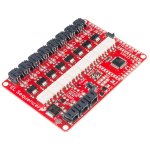
There are two boards one is a stand alone with a ATmega 328p called the EL Sequencer looks like this. el_sequencer.jpg I have a working sketch for this as it uses serial communication.

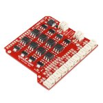
The one I want to switch to so I can use Wifi and E1.31 is a shield type board called SparkFun EL Escudo Dos and it looks like this. sparkfun_escudo.jpg You have to solder headers on it to attach to the main board.

I want to connect 3 of these boards together and doing it with xbee wireless serial is a bit pricy for each one would require 2 xbees @$25 ea, and a adapter for the xbee at @25ea, $75 total per setup plus the cost of the board at $35 is $110 per costume where as with the wifi setup its about $25 + $7 = $32 per costume
Both of them are only 8 outputs/channels.

Worth checking; The ESP8266 only has a 3.3V outputs whereas the Mega etc have 5V outputs. Does the EL board work with 3.3V inputs? I
yes can work on 3.3v

Thanks for the input.
 
Ok so I took a shot at the code. Seems like there is a better way to determine the correct output to turn on then all of the IF statements.

I have not tried this code, although it does compile..does that count?

Code:
// Wemos D1 E1.31 - 8 channel sketch for Sparkfun EL Escudo Dos shield
//Spark Fun link https://www.sparkfun.com/products/10878

#include <ESP8266WiFi.h>
#include <E131.h> // Copyright (c) 2015 Shelby Merrick http://www.forkineye.com

// ***** USER SETUP STUFF *****
const char ssid[] = "<YOUR_SSID>";  // replace with your SSID.
const char passphrase[] = "<YOUR_PASSWORD>"; // replace with your PASSWORD.
const int universe = 1; // this sets the universe number you are using.

//set Pin for Sequencer channels (pins 2 through 9)
#define CHAN_1_PIN_ID 2
#define CHAN_2_PIN_ID 3
#define CHAN_3_PIN_ID 4
#define CHAN_4_PIN_ID 5
#define CHAN_5_PIN_ID 6
#define CHAN_6_PIN_ID 7
#define CHAN_7_PIN_ID 8
#define CHAN_8_PIN_ID 9


//intensity value to turn on channels
//default is 127 so that anything above 127 turns output on since they are not dimmable.
#define CHANNEL_TRIGGER_LEVEL 127

E131 e131;

void setup() {
  Serial.begin(115200);
  int x;
  // Step through all eight EL channels (pins 2 through 9)
  //set them to OUTPUT and OFF
  for (x=2; x<=9; x++)
  {
  pinMode(x, OUTPUT);
  digitalWrite(x, LOW);
  } // end set up the output ports

  /* Choose one to begin listening for E1.31 data */
  e131.begin(ssid, passphrase);               /* via Unicast on the default port */
  // e131.beginMulticast(ssid, passphrase, universe); /* via Multicast for Universe 1 */
}

void loop() {
  /* Parse a packet */
  uint16_t num_channels = e131.parsePacket();

  /* Process channel data if we have it */
  if (num_channels) {
    Serial.println("we have data");
    if (e131.data[CHAN_1_PIN_ID] > CHANNEL_TRIGGER_LEVEL) {
          digitalWrite(2, HIGH);
        }
        else {
          digitalWrite(2, LOW);
        }
    if (e131.data[CHAN_2_PIN_ID] > CHANNEL_TRIGGER_LEVEL) {
          digitalWrite(3, HIGH);
        }
        else {
          digitalWrite(3, LOW);
        }
  if (e131.data[CHAN_3_PIN_ID] > CHANNEL_TRIGGER_LEVEL) {
          digitalWrite(4, HIGH);
        }
        else {
          digitalWrite(4, LOW);
        }
  if (e131.data[CHAN_4_PIN_ID] > CHANNEL_TRIGGER_LEVEL) {
          digitalWrite(5, HIGH);
        }
        else {
          digitalWrite(5, LOW);
        }
  if (e131.data[CHAN_5_PIN_ID] > CHANNEL_TRIGGER_LEVEL) {
          digitalWrite(6, HIGH);
        }
        else {
          digitalWrite(6, LOW);
        }
  if (e131.data[CHAN_6_PIN_ID] > CHANNEL_TRIGGER_LEVEL) {
          digitalWrite(7, HIGH);
        }
        else {
          digitalWrite(7, LOW);
        }
  if (e131.data[CHAN_7_PIN_ID] > CHANNEL_TRIGGER_LEVEL) {
          digitalWrite(8, HIGH);
        }
        else {
          digitalWrite(8, LOW);
        }
  if (e131.data[CHAN_8_PIN_ID] > CHANNEL_TRIGGER_LEVEL) {
          digitalWrite(9, HIGH);
        }
        else {
          digitalWrite(9, LOW);
        }
        
  } //end num_channels
} // end void loop
 
Hi, that’s a pretty good attempt. If I could make a couple of comments.

The GPIOs on the ESP8266/Wemos are not quite as logical as the Mega. There are 16 gpios numbered from 0 to 15.
GPIO 0 (D3). Can be used as a GPIO but also controls how the ESP boots up and needs to be high when powered up for normal run and low when powered up for flashing. More on this later in the project just don’t use it for now.
GPIO 1 (Tx). This is the default Tx pin for serial communication but can also be used as a GPIO if the function is changed with ‘pinMode(<PIN>, FUNCTION_<FUNCTION>);’ or more specifically for this pin ‘pinMode(1, FUNCTION_3);’. More on this later in the project just don’t use it for now.
GPIO 2 (D4). A standard GPIO pin use as normal.
GPIO 3 (Rx). This is the default Rx pin for serial communication but can also be used as a GPIO if the function is changed with ‘pinMode(<PIN>, FUNCTION_<FUNCTION>);’ or more specifically for this pin ‘pinMode(3, FUNCTION_3);’. More on this later in the project just don’t use it for now.
GPIO 4 (D2) & GPIO 5 (D1). Standard GPIO pins use as normal.
GPIOs 6, 7, 8, 9, 10 & 11. These GPIOs are used to read from the on board flash memory, any attempt to use them will result in a crash. Don’t use them.
GPIO 12 (D6), 13 (D7) and 14 (D5). Standard GPIO pins use as normal.
GPIO 15 (D8). Can be used as a GPIO but also controls how the ESP boots up and needs to be low when powered up for normal run. It has a pull down resistor on most of the boards and can be used as normal, just be aware that if you use a pull up on this pin for any reason it could lead to problems.
Just for reference ADC (A0). An input only pin, can be useful if you run out of pins.

EDIT: I left out the 17th GPIO, GPIO16 (D0) as this is quite often used for deep sleep but it appears that the EL shield uses this as one of the inputs.
The mega uses GPIOs: 2, 3, 4, 5, 6, 7, 8 & 9 in that order.
The Wemos D1 will need to use GPIOs: 16, 5, 4, 0, 2, 14, 12 & 13 to keep the order the same. I haven’t checked the 5V and ground pins but it looks like the EL board will work as a shield with the D1.


<Text removed (strike didn't work)>

You’ll need to amend this block.
Code:
//set Pin for Sequencer channels (pins 2 through 9)
#define CHAN_1_PIN_ID 2
#define CHAN_2_PIN_ID 3
#define CHAN_3_PIN_ID 4
#define CHAN_4_PIN_ID 5
#define CHAN_5_PIN_ID 6
#define CHAN_6_PIN_ID 7
#define CHAN_7_PIN_ID 8
#define CHAN_8_PIN_ID 9
Unfortunately because the pin numbers don’t follow on you’ll have initialise and set the outputs long hand or setup an array to loop through.
Code:
  int x;
  // Step through all eight EL channels (pins 2 through 9)
  //set them to OUTPUT and OFF
  for (x=2; x<=9; x++)
  {
  pinMode(x, OUTPUT);
  digitalWrite(x, LOW);
  } // end set up the output ports

This next part, is not going to do what you want or the names have thrown me.
Code:
    if (e131.data[CHAN_1_PIN_ID] > CHANNEL_TRIGGER_LEVEL) {
          digitalWrite(2, HIGH);
        }
        else {
          digitalWrite(2, LOW);
Code:
e131.data[CHAN_1_PIN_ID]
As it stands you are using the pin number where I think you intended to use a channel number. e1.31.data[] is an array with up to 512 channel values in it. The positions in the array are 0 to 511. To read the channel 1 data value you would do this.
Code:
e131.data[0]
The position of data is offset by -1 when compared to its channel number.
If as I think, you wanted to send channel 1 data, to the pin that is allocated to channel 1, it should look like this.
Code:
    if (e131.data[0] > CHANNEL_TRIGGER_LEVEL) {
          digitalWrite(CHAN_1_PIN_ID, HIGH);
        }
        else {
          digitalWrite(CHAN_1_PIN_ID, LOW);

It's always good when things complie.
 
Last edited:
Barnabybear, thanks for the detailed response. I've edited my code per your comments.

Question: In my serial code, we needed a header text to be sure to sync, is that needed here or is that already part of the E1.31 library we are using?

In lieu this code
if (e131.data[0] > CHANNEL_TRIGGER_LEVEL) {
digitalWrite(CHAN_1_PIN_ID, HIGH);
}
else {
digitalWrite(CHAN_1_PIN_ID, LOW);
I used this as it is less code. I got it from my original sketch that MartinMueller helped with.
digitalWrite(output_1, (e131.data[0] > 127) ? HIGH : LOW);

Code:
// Wemos D1 E1.31 - 8 channel sketch for Sparkfun EL Escudo Dos shield
//Spark Fun link https://www.sparkfun.com/products/10878

#include <ESP8266WiFi.h>
#include <E131.h> // Copyright (c) 2015 Shelby Merrick http://www.forkineye.com

// ***** USER SETUP STUFF *****
const char ssid[] = "<YOUR_SSID>";  // replace with your SSID.
const char passphrase[] = "<YOUR_PASSWORD>"; // replace with your PASSWORD.
const int universe = 1; // this sets the universe number you are using.


// this sets the pin numbers to use as outputs.
const int output_1 = 16; //the pin to use as output 1 (D0)
const int output_2 = 5;  //the pin to use as output 2 (D1)
const int output_3 = 4;  //the pin to use as output 3 (D2)
const int output_4 = 0;  //the pin to use as output 4 (D3)
const int output_5 = 2;  //the pin to use as output 5 (D4)
const int output_6 = 14; //the pin to use as output 6 (D5)
const int output_7 = 12; //the pin to use as output 7 (D6)
const int output_8 = 13; //the pin to use as output 8 (D7)


E131 e131;

void setup() {
  Serial.begin(115200);
  // set the pins chosen above as outputs.
  pinMode(output_1, OUTPUT);
  pinMode(output_2, OUTPUT);
  pinMode(output_3, OUTPUT);
  pinMode(output_4, OUTPUT);
  pinMode(output_5, OUTPUT);
  pinMode(output_6, OUTPUT);
  pinMode(output_7, OUTPUT);
  pinMode(output_8, OUTPUT);

  // set the pins chosen above to low / off.
  digitalWrite(output_1, LOW);
  digitalWrite(output_2, LOW);
  digitalWrite(output_3, LOW);
  digitalWrite(output_4, LOW);
  digitalWrite(output_5, LOW);
  digitalWrite(output_6, LOW);
  digitalWrite(output_7, LOW);
  digitalWrite(output_8, LOW);
  
  /* Choose one to begin listening for E1.31 data */
  e131.begin(ssid, passphrase);               /* via Unicast on the default port */
  // e131.beginMulticast(ssid, passphrase, universe); /* via Multicast for Universe 1 */
}

void loop() {
  /* Parse a packet */
  uint16_t num_channels = e131.parsePacket();

  /* Process channel data if we have it */
  if (num_channels) {
    Serial.println("we have data");

    digitalWrite(output_1, (e131.data[0] > 127) ? HIGH : LOW);
    digitalWrite(output_3, (e131.data[1] > 127) ? HIGH : LOW);
    digitalWrite(output_3, (e131.data[2] > 127) ? HIGH : LOW);
    digitalWrite(output_4, (e131.data[3] > 127) ? HIGH : LOW);
    digitalWrite(output_5, (e131.data[4] > 127) ? HIGH : LOW);
    digitalWrite(output_6, (e131.data[5] > 127) ? HIGH : LOW);
    digitalWrite(output_7, (e131.data[6] > 127) ? HIGH : LOW);
    digitalWrite(output_8, (e131.data[7] > 127) ? HIGH : LOW);
    }//end we have data

} // end void loop
 
Hi, that looks good. You are correct e1.31 library takes care of the header as its more complicated than the serial one. I’ll keep an eye on the thread to see how you get on.
 
Awesome, thanks for you help. I’m waiting. For the board to come in so I can test. I’ll report back.


Sent from my iPhone using Tapatalk
 
Hi, just as a side note. Don’t get sucked into thinking that when coding less lines is better. I’m just working on some stuff tonight and I’ve put loops in it, which keeps the line count down but it’s not running fast enough so I’m going to have to take all the loops out and type each line to gain some time, loops are convenient but slow.
 
This has been an excellent learning experience so far thanks to your sharing . I have been using this extensively and hit a wall as to how to incorporate the Neo Pixel lib and control a few pixels along side a few motors .

Is it possible or just wishful thinking ?
 
Hi, I don’t see why this can’t be achieved. I’m not sure if the servo library and the neo pixel library will play well together, sometimes the different library’s use the same timers and that can make things tricky. I’m guessing you’re not needing lots of pixels mainly eyes and the odd bit of other stuff. How many servos and pixels are you needing?
 
Hi, I don’t see why this can’t be achieved. I’m not sure if the servo library and the neo pixel library will play well together, sometimes the different library’s use the same timers and that can make things tricky. I’m guessing you’re not needing lots of pixels mainly eyes and the odd bit of other stuff. How many servos and pixels are you needing?
Hi
My goal is to have each prop independently controlled via 1 wemos per prop .
For simplicity all is 5v . I was hoping to avoid adding another esp-01 just for the few eye pixels in each prop .
Skulls are using a single servo each for jaw movement only and the wolves are using 3 servos each .
 
Hi
My goal is to have each prop independently controlled via 1 wemos per prop .
For simplicity all is 5v . I was hoping to avoid adding another esp-01 just for the few eye pixels in each prop .
Skulls are using a single servo each for jaw movement only and the wolves are using 3 servos each .

Hi, cool. How many pixels and could they be dumb? Dumb RGB would be much easier if only used for eyes.
 
I only have 12v dumb so trying to avoid it . I did try the servo sketch and added the adafruit neo pixel lib .
Configured and added universe 2 with 15 pixels and gave it a play .
Some of the pixels worked but randomly and I could not determine color order or channel # so I said uncle :)

But it was intriguing that the pixels light up .
 
Hi, hand drawn schematic below. The 270R resistor is to protect the wemos outputs, if you don’t have one 330R or 220R will do. This switches the connection to ground (low side) so can be used for voltages greater than 5V if needed. There are 6 GPIOs that I would start with: 12, 13, 14, 15, 4 & 5. You can repeat this circuit for each GPIO / channel you wish to control; you may need current limiting resistors for the LEDs dependant on which you use.


Once you get some bits wired up if you need help with the sketch let me know.

View attachment 38974

EDIT:
I didn't lable the pins on the FET.
Top = Drain.
Side = Gate.
Bottom = Source.

Hi BarnabyBear

I managed to find a string of 5v Dumb rgb and noticed that the output does not switch and keeps the leds on . It appears to be anode switching on regular leds . Does this circuit invert the output to cathode switching ? Interestingly your code works perfectly with regular leds .
I guess it is not possible to invert the output in firmware or you would have done it . Had I tested this for just rgb before , I would have just used regular leds :)
Thanks again for this .
 
Hi, the output can be inverted, it's midnight this side so not much I can do tonight. Link or photo the parts you have and I'll sort something in the moring.
 
Hi, the output can be inverted, it's midnight this side so not much I can do tonight. Link or photo the parts you have and I'll sort something in the moring.

Hi Barnabybear

I have 2 strings of these but the 5v version.

I was hoping to get 3 servos working and some leds . Servos are the priority ! :)

Could always piggy back an esp-01 and use pixels for the eyes .
 
Back
Top