Questions about Buck Converter 12V to 5V

Wacamoe

Member
Hello all,

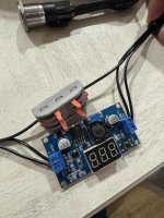
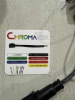
I purchased an addressible momentary switch for my "push for music" setup (https://www.amazon.com/dp/B0988V21SM) and I have a 12V power system. My goal was to put a buck converter near the pole, and use that to step down to 5V for the switch, since it's the only 5V pixel I have in my display. (https://www.amazon.com/dp/B08JZ5FVLC)

I got all the parts, and wired it up, but it didn't work in my test setup.

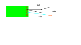
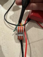
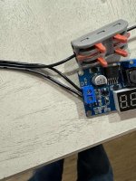
Hinkx Pix Controller (12V) -> Buck converter > Switch is what I did. (attached)

However, I'm getting 12V in the output regardless. I tried "cutting" and soldering the 5V diagram on the back, but either i dont understand what I'm doing, or I have faulty cuips. Regardless, I'm replacing the Bucks with something better and clearer to me. (https://www.amazon.com/Adjustable-Converter-Step-Down-Regulator-Stabilizer/dp/B081N6WWJS)

My question is, am I going about this correctly, or am I missing something more fundamental?

TIA
 

Attachments

  • buck_wiring_diagram.png
    buck_wiring_diagram.png
    2.8 KB · Views: 20
I have some of those buck converters in my show. You need a small screw driver to get the proper output voltage. After 5 years, some of them are starting to have an issue with the adjustment and the voltage is wandering a bit. It looks like the potentiometer is developing a "bad spot" and it can no longer be adjusted to 5v. Other than that, they work fine.

Your drawing was incomprehensible wrt to the buck you are showing.

I assume you wanted to use the 12v from the controller as an input to a buck converter and take the 5v on the buck output to drive the Pixel. That should work just fine. Keep in mind that the data line is always at 5V so no adjustments to the data line are needed.
 
Have you tried using a tiny screwdriver to turn that screw (potentiometer maybe?)? The link says it's adjustable so i would assume that's where you adjust it

Sent from my Pixel 7 Pro using Tapatalk
 
Almost easier building a 5v regulator from a 7405 ... as much as I like doing things the hard way, getting a fixed output regulator works too. I use 12-24v to 5v (25watts) converters for years now. They are sealed so no worries about weather. I do use 12v for power distribution to the 5v regulator for a few OUT OF THE WAY 5v props that get their signal (ws2811) from other 12v props.

Just a thought.
 
Easy? Yes but horrible. The 7805 is a regulator. It dumps the 7v ass heat and is very load sensitive. The buck converters are choppers that adjust the frequency to deliver the voltage and current to the load and dispenses (relativly) very little heat.
 
Assuming that they're talking about a single (only 1) 60 mA pixel (typical WS2811 pixel), I don't think it's horrible. For a heavier load than that, yes, a buck converter would be much better suited, but dropping 12V down to 5V at 60mA would be 0.42 W, which is not a big deal in many circumstances. And unless you're talking about how the power dissipation depends on load, I have no idea what's meant by 'load sensitive'.

Or course, making the parts work that are on-hand is the better solution.
 
So adjusting the screw i was able to get to 5V on the output, so thanks all for that. The LED still doesn't turn on in the button - can't tell if I burned it out accidently or wired it incorrectly.

I assume I can just hookup the 3 wires that I would typically hook up for XConnect LEDS - in this case the black wire is positive, the red is data and the Yellow is ground - however, the LED doesn't light up. Out of the buck converter I have the shared ground and the V+ Out at 5V.

Am I missing anything else here? The NO/NC shouldn't have to be connected to anything, I wouldn't the common would either as I would imagine those are for the switch and not the LED.
 
If you applied 12v to a WS2811 chip which is rated at 7v max, you most likely let out the magic smoke/ However, I would still check to see if your 5v + data is working by connecting an independent 5v pixel to make sure it is working.
 
You could use the data out to connect to some 12v power injected pixels and see if you get signal past the button pixel.
 
So Amazon replacement, new buck converter and still no lights......I must be missing something dumb. I'm posting more pictures now but something must going over my head....

The buck converter reads 4.9v out. Multimeter is reading the same coming out, but to the data line it's more like 0.8v coming out.
 

Attachments

  • IMG_0107.jpg
    IMG_0107.jpg
    126.5 KB · Views: 22
  • IMG_0108.jpg
    IMG_0108.jpg
    103 KB · Views: 24
  • IMG_0109.jpg
    IMG_0109.jpg
    109.6 KB · Views: 27
  • IMG_0106.jpg
    IMG_0106.jpg
    113.8 KB · Views: 14
Last edited:
data = 0.8 indicates no data. Measure the data line on a working output at the controller (one that has lights showing colors) and you should read something between 1.5v and 2.3v. 0.8v indicates there is no data coming out. An oscilloscope could tell you more about the data line.
 
I would check your connections. Are those 3 port gray lever splice connectors 3 individual splices or does it join all the wires together? And are you stripping the insulation far enough off the wires to make a good connection with those lever splice connectors?
Go back and check ALL your wire connections for proper termination.
Then find yourself a single 5V pixel and test that on your setup instead of using the chroma switch.
I suggest your twist and solder your connections and not use those lever splice connectors. IMO
 
i replaced all the connectors from soldered to the splicers to rule some of that out, but thats a valid point. Unfortunately i have zero 5v pixels on hand - will try and figure out where to source from.

Additionally - i pulled a working prop out of my display and replaced this in line so i know data is coming through to this connection and still nothing. Im wondering if the circut require some of the "C" and "NC/NO" wirring to be part of the circut for the LED but I can't find anything about that anywhere....

All this for a button LOL
 
Your switch appears to be serving as a relay and I would assume the wiring method would be similar . You definitely need determine if you want your circuit n/o or n/c .
 
I'm no expert but would it be easier to get a 12v button and just add a relay in-line or something?

APIELE 16mm Momentary Push Button Switch On Off Stainless Steel with 12V LED Angel Eye Head for 16mm 0.63" Mounting Hole with Wire Socket Self-reset (Blue) https://a.co/d/j501JDU

Sent from my Pixel 7 Pro using Tapatalk
 
Last edited:
if using the Hinks as data source ,be certain the outputs are enabled and configured.

try this if the purpose is to test the ws2812 in the switch , apply the 5v to n/o and gnd to common data to red . press the button while data is being sent from the Hinks. Voila.

You may need to write some code to use this switch as intended .

Else try here

https://www.adafruit.com/product/5236
 
Last edited:
I'm no expert but would it be easier to get a 12v button and just add a relay in-line or something?

APIELE 16mm Momentary Push Button Switch On Off Stainless Steel with 12V LED Angel Eye Head for 16mm 0.63" Mounting Hole with Wire Socket Self-reset (Blue) https://a.co/d/j501JDU

Sent from my Pixel 7 Pro using Tapatalk

I actually already have a switch relay system for my push for music system - the point here was to have a button with an LED i can control in xlights.
 
Back
Top