This post is to help explain "What the heck is a SSR?"
The SSR is a Solid State Relay. To put it in simplest terms, there are two switches to turn on one channel. The signal from the controller to turn on the lights is sent to the SSR. It goes into the first "switch" the Opto Isolator. The ‘Opto’ is a photo sensor and LED. This component’s job is to protect the controllers from the 120v that is on the SSR. The second ‘switch’ is the Triac, which is operated by the ‘Opto’. The Triac switches the 120v that goes to the lights. Both components need resistors in front of them to limit the current to operate them.
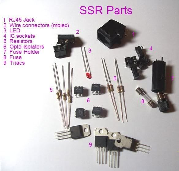
The parts of a SSR
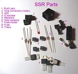
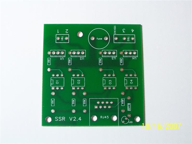
Below is a picture of a bare pcb of the SSR
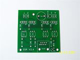
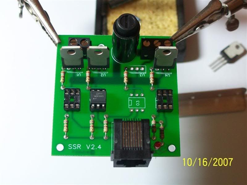
Parts assembly… I left some parts off, as to see the silkscreen and how the parts are placed. Make special note of the dot on the Opto , and the tab of the Triac. These parts must be installed that way. The resistor values are different for the Opto’s and Triacs. The 750ohm are installed before the Opto, and the 180ohm is installed before the Triac. The resistors are not current directional, so installation direction is not important. Although, it looks very nice when they are all oriented the same way. The LED is directional. The short lead goes into the pad on the flat side of the silk screened outline.
After your SSR is assembled, it needs an enclosure. There are many different ways to do things from here. You can wire extension cords to them or use wall outlets. You do what suit your needs.
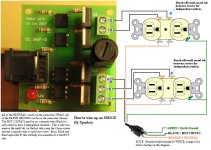
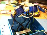
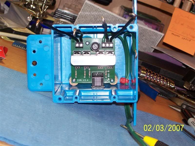
This is an example of the using a wall box and outlets. You will notice that there is a piece of aluminum on the Triacs in the pics. This is a heatsink. Good insurance to have, but is debated to be ‘needed’

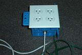
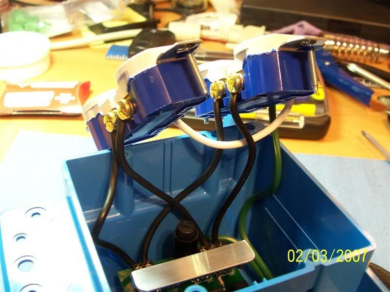
When you wire the outlets, do them all the same. This is so the channels are all in the same location per the 4 plugs. You must break off the jumper tab on the ‘hot’ side of the outlets so you have 4 separate outlets. You can leave the jumper on the common side to save on wires.
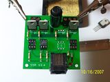
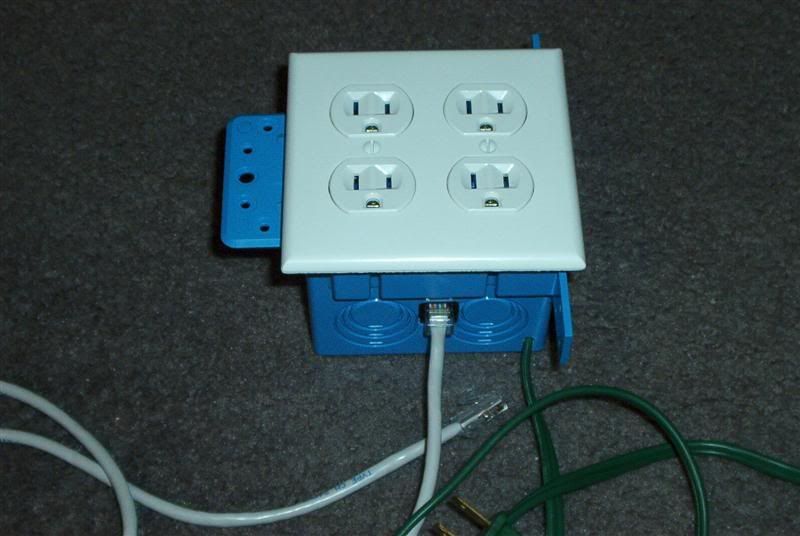
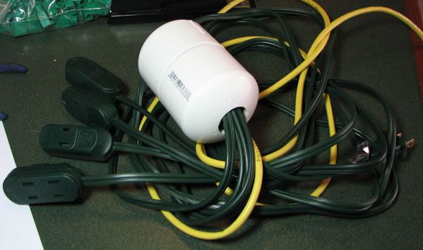
A completed assembly…
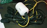
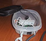
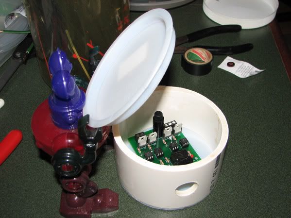
You can get creative to make things fit you needs. Here are some really neat ways to put them in enclosures. The link under The Pod gives a step by step assembly, which is the basic principle of assembling the SSR.
"The Pod" How To
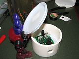
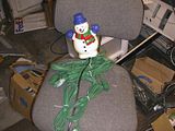
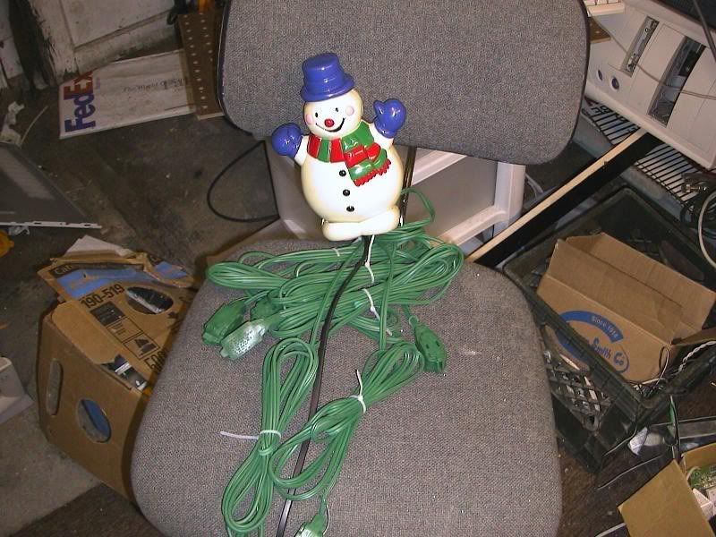
You can even use them as part of your display…..
Just remember.... The SSRs are carrying 120VAC. Please BE CAREFUL! Triple check your work, make sure no stray strands of wire are about, no wires are laying on the Triacs (they possibly can get hot and melt wire insulation) When testing them, plug them into a GFIC outlet just to be safe.
And don't forget, have fun and enjoy yourself.
The SSR is a Solid State Relay. To put it in simplest terms, there are two switches to turn on one channel. The signal from the controller to turn on the lights is sent to the SSR. It goes into the first "switch" the Opto Isolator. The ‘Opto’ is a photo sensor and LED. This component’s job is to protect the controllers from the 120v that is on the SSR. The second ‘switch’ is the Triac, which is operated by the ‘Opto’. The Triac switches the 120v that goes to the lights. Both components need resistors in front of them to limit the current to operate them.
The parts of a SSR
Below is a picture of a bare pcb of the SSR
Parts assembly… I left some parts off, as to see the silkscreen and how the parts are placed. Make special note of the dot on the Opto , and the tab of the Triac. These parts must be installed that way. The resistor values are different for the Opto’s and Triacs. The 750ohm are installed before the Opto, and the 180ohm is installed before the Triac. The resistors are not current directional, so installation direction is not important. Although, it looks very nice when they are all oriented the same way. The LED is directional. The short lead goes into the pad on the flat side of the silk screened outline.
After your SSR is assembled, it needs an enclosure. There are many different ways to do things from here. You can wire extension cords to them or use wall outlets. You do what suit your needs.
This is an example of the using a wall box and outlets. You will notice that there is a piece of aluminum on the Triacs in the pics. This is a heatsink. Good insurance to have, but is debated to be ‘needed’
When you wire the outlets, do them all the same. This is so the channels are all in the same location per the 4 plugs. You must break off the jumper tab on the ‘hot’ side of the outlets so you have 4 separate outlets. You can leave the jumper on the common side to save on wires.
A completed assembly…
You can get creative to make things fit you needs. Here are some really neat ways to put them in enclosures. The link under The Pod gives a step by step assembly, which is the basic principle of assembling the SSR.
"The Pod" How To

You can even use them as part of your display…..
Just remember.... The SSRs are carrying 120VAC. Please BE CAREFUL! Triple check your work, make sure no stray strands of wire are about, no wires are laying on the Triacs (they possibly can get hot and melt wire insulation) When testing them, plug them into a GFIC outlet just to be safe.
And don't forget, have fun and enjoy yourself.
Attachments
Last edited:
")