Vastelec FM02: Difference between revisions
Ukewarrior (talk | contribs) No edit summary |
|||
| (180 intermediate revisions by 3 users not shown) | |||
| Line 1: | Line 1: | ||
==The FM Transmitter with DIY possibilities == | |||
[[Image:FM02_beauty_shot.jpg|FM-02]] | |||
<br style="clear:both" /> | |||
[[Image:Fm02_beauty_shot_2.jpg|thumb|right|click on the picture for a larger version]] | |||
[[Image:Fm02_beauty_shot_3.jpg|thumb|right|click on the picture for a larger version]] | |||
The FM02 is a two board FM transmitter. It accepts a stereo audio source and outputs a stereo FM broadcast signal on the frequency shown on the LED display. It comes just as shown in the picture above. | |||
< | |||
[[ | It is rated at 30mw (that's milli-watts) of transmission power. For most Christmas DIYers this is a nearly perfect amount of power. It will transmit a clear signal for about 2 blocks or 1/4 mile. Why is this good? Because it is illegal in the USA to transmit other then very low amounts of FM radiation without an FCC license. | ||
<p> | |||
Skip to this section for more details: [[http://www.doityourselfchristmas.com/wiki/index.php?title=Vastelec_FM02#Why_you_should_care_about_the_power_of_your_transmitter FCC Rules]] | |||
</p> | |||
<p> | <p> | ||
</p> | </p> | ||
The FM02 is not a complete unit ready for use. | The FM02 is not a complete unit ready for use. | ||
Instead, it bridges the gap between an out-of-the-box solution, and a build-your-own unit that starts with a bare PCB and a bag of parts. | Instead, it bridges the gap between an out-of-the-box solution, and a build-your-own unit that starts with a bare PCB and a bag of parts. | ||
< | <p> | ||
The FM02 is very small, but packs in a nice set of features. </p><p> | The FM02 is very small, but packs in a nice set of features. </p><p> | ||
Key to these is the use of PLL (Phase Locked Loop) technology. PLL keeps the transmitter locked into the designated transmitting frequency without it drifting up or down. This frequency drift WILL occur on other FM transmitters without PLL as the temperature around the unit goes up or down. | Key to these is the use of PLL (Phase Locked Loop) technology. PLL keeps the transmitter locked into the designated transmitting frequency without it drifting up or down. This frequency drift WILL occur on other FM transmitters without PLL as the temperature around the unit goes up or down. | ||
| Line 24: | Line 29: | ||
</p><p> | </p><p> | ||
You will need the following items added to your FM02:</p><p> | You will need the following items added to your FM02:</p><p> | ||
- Power. | - Power. For details, see the POWER section below. 100ma is enough current.</p><p> | ||
- An Antenna. Never power your unit without an antenna.</p><p> | - An Antenna. Never power your unit without an antenna.</p><p> | ||
- A mounting enclosure. You will need to mount the FM02 boards somewhere safe and dry.</p> | - A mounting enclosure. You will need to mount the FM02 boards somewhere safe and dry. | ||
- Connection to a stereo Audio Source. The FM02 has a 3.5mm audio jack.</p> | |||
== About VAST Electronics== | == About VAST Electronics & Product Warranty== | ||
[http://www.vastelec.com/ | [http://www.vastelec.com/ Vendor's Website] | ||
[http://www.doityourselfchristmas.com/wiki/images/f/f7/FM-Transmitter.pdf Data Sheet] | [http://www.doityourselfchristmas.com/wiki/images/f/f7/FM-Transmitter.pdf Data Sheet] | ||
VAST warranties the FM02 for two years. The trick with this warranty is that it requires the product to be returned for repair to VAST in China. ''IF'' you can catch a group buy in progress on doityourselfchristmas.com, you can also request a replacement when that order is placed with VAST. | |||
You can also receive warranty service from the units purchased directly from www.radiant-holidays (former WLC ventures). | |||
==Pictures of FM02's in enclosures== | |||
Each FM02 installation is unique ! | |||
'''A gallery of over 25 different installations with pictures and 'how to build notes' is available.''' | |||
Click Here to see many FM02 installations: [[FM02_Gallery]] | |||
== Power Requirements == | == Power Requirements == | ||
[[Image:SURE_lm317.jpg|thumb|right|click on the picture for a larger version]] | |||
''Do NOT power it up without an antenna.'' You don't need to have your 'real' antenna ready for this. You can put an sma-to-BNC adapter on and then stick a 12" piece of wire into the center of the BNC connector. This will dissipate the RF energy just fine. Just be sure you don't enlarge the hole inside the BNC. | |||
<p> | |||
''DO NOT apply anything GREATER then REGULATED 9V-16V DC to your unit. 12V DC is the ideal voltage to shoot for.'' If you aren't sure, then ask for help in the forums. Use a meter to check the voltage first. If all you have is a wall-wart that is labeled 12V, then that is most likely NOT regulated. A simple test of the output voltage with a meter will tell the tale. | |||
I use one of the voltage regulators from Sure Electronics with my unit (Part number:PS-SP12113). These are about $5 online. | |||
</p> | |||
While the unit will 'run' on the voltages noted above, '''you should try to run it on 12V.''' | |||
If you operate the unit at a reduced voltage, this only drops the mean voltage feeding the chip and thus drops the chips ability to function correctly. By turning down the operating voltage, (that is one way to reduce that hissing pilot level), but your also reducing the correct operating voltage for not just the FM chip, but the microprocessor, the PLL, the display, the final RF amp, the whole thing, not to mention reduced range and added distortions in the audio paths within the TX and FM chip itself. | |||
A good example of this is taking a portable battery operated radio and put a weak battery in it and hear how distorted and low volume the audio is compared to a fresh correct voltage battery. | |||
<p> | |||
You need very little power for an FM02. A power supply rated at only 100ma is sufficient. | |||
</p> | |||
When you connect power to the FM02 it is '''VERY''' important that you get your positive(+) and your negative(-) correct. | |||
<p> | |||
'''If you hook up the power incorrectly, you can easily damage/ruin the unit.''' | |||
</p> | |||
== Do you have a HUM ? == | |||
Many folks will experience some ''HUM'' in the transmitted audio. This is normal. The good news is that you should be able to eliminate this hum with the use of a ''Ferrite Bead.'' | |||
<p> | |||
(See ''Audio'' Section below for poor audio quality problems) | |||
</p> | |||
<p> | |||
(See the ''Ways to improve the sound quality for Advanced Users'' Section below if you hear a 'shhhhhhhhing' sound) | |||
</p> | |||
If you look at the tech that is already in your house, you will see these beads on lots of things. They are in power cords, and even ethernet cables. I get mine for free this way. I just cut them out of these cords. | |||
If you work in an office, you can usually go to the cube of the LAN/Networking guys and ask them for an excess power cord with one of these 'bumps' in the cord. They usually have dozens of extras laying around. | |||
As far as size, you want to be able to wrap the wire through the hole and around the perimeter 3 times for maximum effect. You also need to wrap it tightly and secure it in place with a nylon tie wrap. So, it depends on the size of the wire that comes out of your wall wart, you need to have a diameter that can fit three wraps of the wire and the tie. | |||
If you use a Wall Wart for power, you absolutely need a ferrite bead on the power cord coming out of the wall wart. | |||
It is also a good idea to put a bead on the audio cable coming out of the PC. | |||
The beads should be placed on the FM02 end of the cable. | |||
Sometimes, it helps to put a ferrite bead on the audio cable between the PC and transmitter. | |||
'''NOTE''': it never hurts to put one or more ferrite beads on your cables. They may or may not eliminate your ''HUM'', but they never make it worse. | |||
Some Beads split in half, some don't ! | |||
[[Image:Ferrite_1.jpg|left|A Split Ferrite bead]] | |||
[[Image:Ferrite_2.jpg|right|A multi wrap Ferrite bead]] | |||
There are some good pictures in the wiki-pedia-: | |||
http://en.wikipedia.org/wiki/Ferrite_bead | |||
== Audio == | |||
[[Image:3.5mm_stereo_plug.jpg|right|thumb|3.5mm stereo plug]] | |||
The FM02 has a standard 3.5mm stereo jack for the wire that is carrying your audio signal. | |||
There is one key point about the audio. | |||
It works best with a ''line level'' audio input. | |||
The ''Audio Out'' jack on a PC is NOT ''line level''. | |||
Line Level is a very low volume level signal. | |||
The Volume level on your PC needs to be set very low, barely audible. | |||
If you ''overdrive'' the audio signal, it will result in a FM transmission that will sound distorted. | |||
. | |||
== Schematic and PCB layout == | |||
[[Image:FM02_Schematic_small_pic.jpg|right|schematic]] | |||
The schematic and PCB layout are documented in a .pdf file. | |||
<p> | |||
This document shows the electronic board schematic and the PCB layout for the main transmitter board. | |||
</p><p> | |||
What is not shown is the information for the 'Display' board of this two board set. | |||
</p> | |||
<p> | |||
</P> | |||
<p> | <p> | ||
[[http://www.doityourselfchristmas.com/wiki/images/1/1a/FM02_Schematic.pdf Click Here for the full Schematic & PCB layout File]]. | |||
</p> | |||
== Detailed Board Dimensions == | == Detailed Board Dimensions == | ||
| Line 135: | Line 247: | ||
</p> | </p> | ||
'''Here is a pdf file that contains a scale outline that will serve as a template for the display board. You would use this to create your own bezel if you want to dress-up your installation:''' [[http://www.doityourselfchristmas.com/wiki/images/e/e2/FM02_cutout_layout.pdf Bezel Template]] | |||
== Antenna == | == Antenna == | ||
The FM02 has an antenna connection that will look a bit unusual to most folks. | The FM02 has an antenna connection that will look a bit unusual to most folks. | ||
It is known as an '''''SMA''''' type of connector. | It is known as an '''''SMA''''' type of connector.<br> | ||
Reference: [http://en.wikipedia.org/wiki/SMA_connector Wiki entry for SMA connector] | |||
It is important when attaching an antenna/converter/cable to this connector that you do not over-tighten it. | |||
The outer part of this connector is a 'press-fit' part. It is possible to simply defeat the resistance of the press fit and cause this part of the connector to fall off! So, if you use a wrench, be very careful, the connector is rated for INCH Pounds of torque. | |||
Most DIY'ers will want to convert this to the '''''BNC''''' type of connector because BNC components are easier to find. | Most DIY'ers will want to convert this to the '''''BNC''''' type of connector because BNC components are easier to find. | ||
The converter shown below will correctly hook to the FM02. SMA is the smaller gold connector. | The converter shown below will correctly hook to the FM02. SMA is the smaller gold colored part of the connector. You can purchase the adapters from [http://www.diyledexpress.com/index.php?main_page=product_info&cPath=21&products_id=175 diyledexpress.com] or from [http://www.ebay.com/itm/SMA-Male-Plug-to-BNC-Female-Radio-Antenna-RF-Coaxial-Connector-Adapter-NEW-/291294771238 ebay]. | ||
<p> | <p> | ||
[[Image:FM02_sma_to_BNC_converter.jpg |center|smatobnc]] | [[Image:FM02_sma_to_BNC_converter.jpg |center|smatobnc]] | ||
| Line 150: | Line 269: | ||
''' You will need to buy or make an antenna. There are MANY different designs for antennas. A large number of DIYers have made a type of antenna known as a dipole. This is an easy to make antenna that will serve almost anyone's needs. Here is a link to a pdf with instructions to make your own: | |||
[http://www.doityourselfchristmas.com/wiki/images/a/a7/How_to_make_a_dipole_antenna.pdf How to Make a Dipole Antenna]<br> | |||
'''More recently, DIYC member Jhinkle published a paper for an antenna design that is easier to build with very good transmission characteristics.'''<br><br> | |||
Here is the link to a posting on the subject. | |||
[http://doityourselfchristmas.com/forums/showthread.php?20264-1-4-Wave-Verticle-Antenna-for-the-FM-02&p=205469#post205469 DIYC discussion thread]<br><br> | |||
You can go directly to the excellent design and build paper at this link: | |||
[http://www.joehinkle.com/DownLoad/Antenna%20Design%20for%20FM.pdf pdf paper for a ground plane antenna] | |||
== What Frequency to Use == | |||
This is real simple, go to this website and find a frequency that is unused. | |||
If there are no unused frequency's, then pick one that is not very powerful and | |||
get your radio out and check it out. If you can't pick up any radio stations at your house, odds | |||
are no one will complain when you start broadcasting on that frequency.<br> | |||
NOTE: There are seasonal radio stations. A open frequency in June may be used in December. You should plan accordingly. | |||
''' | |||
http://www.radio-locator.com/ ''' | |||
== Where can I get one of these wonderful FM transmitters ? == | |||
NB: Vastelec told U.S. distributors in January 2015 that it would no longer manufacture FM02 transmitters. New old stock and used FM02s may be available. | |||
They are usually stocked at [http://www.diyledexpress.com/index.php?main_page=index&cPath=21 DIYLEDExpress] | |||
They are usually stocked at [http://radiant-holidays.com/radiant_holidays/index.php?main_page=index&manufacturers_id=4 Radiant Holidays].(Was WLC Ventures) | |||
These come up as group buys on the [http://doityourselfchristmas.com/forums/forumdisplay.php?18-Group-Buys DIYC forum] from time to time. | |||
They have also been seen for sale on eBay from seller: [http://www.ebay.com/usr/vastelec Vastelec] or user HLLY. | |||
== RDS hookup information == | |||
'''This section involves modifying your FM02.''' | |||
'''If you do this, you void the warranty.''' | |||
Here is a picture of hooking the pira mini-RDS unit up to an FM02 | |||
The green spot on the PCB is the RDS data hookup point. | |||
The red spot is a section of the PCB that was scrapped away revealing the copper. | |||
This is used a a soldering point for the ground. | |||
[[Image:FM02_RDS_connection.jpg |center|fm02rds]] | |||
Another View of the GREEN RDS connection spot: | |||
Notice, the insert showing the full schematic of the hookup. | |||
Two capacitors are needed as noted. (220 picofarad and 22 picofarad) | |||
The resistor can be any value within the range noted. | |||
[[Image:FM02_RDS_picture_diagram.jpg |center|fm02rds]] | |||
[[Image:RDS_hookup_diagram.jpg |center|hookupdetail]] | |||
Pira Mini-RDS hookup diagram: | |||
[[Image:Standard_RDS_Connection.jpg |center|minirdshookupdetail]] | |||
'''Additional Modifications''' | |||
<p> | |||
</p> | |||
This optional modification is noted on the pira mini-RDS datasheet, but not implemented on the mini-RDS board from pira: | |||
You can add a status LED to the mini-RDS board between pin 1 and ground, with a 2.2k Ohm resistor. | |||
It blinks +- once per second when on, and really fast / almost steady on when transmitting RDS data to the transmitter... | |||
. | |||
== Why you should care about the transmitting power of your transmitter (FCC regulations)== | |||
It's real simple: Do not transmit on a channel that is already in use by a commercial entity that can be heard in your location. | |||
The easiest way to do that is to not buy more transmitter then you need. | |||
That is why the FM02 is such a good choice. Below is the official FCC (USA) verbiage discussing low power FM transmissions. | |||
Did you know if you use an FM transmitter the FCC can inspect your transmitter at any time without a search warrant?!! It's true. | |||
If the FCC finds you operating equipment that is in violation, you must give them your transmitter so they can destroy it ! If you don't, you will face a large fine. | |||
Read through this FCC website discussing the use of an FM transmitter as an 'unlicensed' operator. | |||
Click here: [http://transition.fcc.gov/eb/otherinfo/inspect.html FCC information for unlicensed operators] | |||
''"'''FCC REGULATIONS FOR THE NON LICENSED OPERATION OR RADIO BROADCASTING'''" | |||
PART15: | |||
Unlicensed operation on the AM and FM radio broadcast bands is permitted for some extremely low powered devices covered under Part 15 of the FCC's rules. On FM frequencies, these devices are limited to an effective service range of approximately 200 feet (61 meters). See 47 CFR (Code of Federal Regulations) Section 15.239, and the July 24, 1991 Public Notice. On the AM broadcast band, these devices are limited to an effective service range of approximately 200 feet (61 meters). See 47 CFR Sections 15.207, 15.209, 15.219, and 15.221. These devices must accept any interference caused by any other operation, which may further limit the effective service range. For more information on Part 15 devices, please see OET Bulletin No. 63 ("Understanding the FCC Regulations for Low-Power, Non-Licensed Transmitters").'' | |||
The good folks at RAMSEY have even more detail on their website at: [http://www.ramseyelectronics.com/resource/default.asp?page=fcc FCC rules information regarding transmitter strength] | |||
== Ways to improve the sound quality for Advanced Users == | |||
'''Please note: This should be considered an advanced modification. There are hundreds of FM02 in use by the DIYC community and the vast majority use them without this modification.''' | |||
Some folks want to create the best possible quality sound from their transmitters. | |||
It is possible to hear a small 'shhhhhhhhh-ing' sound in the background of the transmitted sound. | |||
The "shhhhh" issue is not a power supply problem, or audio source problem. The problem is the 19Khz pilot level on the BH1415 chip. | |||
I recommend everyone download the BH1415 data sheet and look at the chip's block diagram and pin layout in order to follow along in solving this "shhhhh" problem. | |||
Pin 19 is the 19Khz pilot tone level. By default, this pin is at a high capacitance state when left open. This pin adjusts the 19Khz pilot level. When it is left unconnected, the pilot level is 30+ percent above the standard 10 percent of modulating the carrier. If the pin is connected to a surface chip cap, this cap may be open or has changed value thus the 19Khz level is still too high. | |||
In order to correct this, a proper modulation monitor or O-scope capable of 100Mhz or more will be needed to adjust properly. | |||
The best capacitor value I have found that brings the 19Khz pilot level down to its standard 10 percent level is a 220pF. The pilot rides at around 11.3 percent. A far cry from the 30+ percent. | |||
Connect the capacitor between Pin 19 of the BH1415 chip and ground. | |||
[[Image:BH1415_block_diagram.jpg |center|fm02block]] | |||
Do not run your FM02 unit at a reduced voltage to correct this shhhhhhing. This only drops the mean voltage feeding the chip and thus drops the chips ability to function correctly. By turning down the operating voltage, that is one way to reduce that hissing pilot level, but your also reducing the correct operating voltage for not just the FM chip, but the microprocessor, the PLL, the display, the final RF amp, the whole thing, not to mention reduced range and added distortions in the audio paths within the TX and FM chip itself. | |||
A good example of this is taking a portable battery operated radio and put a weak battery in it and hear how distorted and low volume the audio is compared to a fresh correct voltage battery. The same happens to the FM02 when power is reduced to try to solve the hissing. It is not solving it at all, it is merely "covering it up" but it is still there and will always be there until the pilot level is correctly adjusted. | |||
The reason why some transmitters using the BH1415 chip have the hissing is because the pilot is left to run wild so that at further distances the stereo transmission will still be received at those greater distances than it would be when the pilot is adjusted to standard. So moral here is either hassy hissy stereo at a distance, or excellent clean smooth sounding stereo audio within the intended range of these low power devices. I would go with the latter because all that hissing over driven pilot level is also decreasing your carrier power and reducing your range anyway. | |||
'''Specifics about the Modification''' | |||
I used a plain ol ceramic disc cap, clipped the leads so they would be short but long enough to allow folding of the capacitor on its side so it rests on the board. | |||
Now on some designs and board layouts, Pin 19 has solder on it, it is soldered to the foil pad on the board, and nothing else. Others have a chip capacitor from Pin 19 to ground, and a few of those have too high a value of capacitor for the proper pilot level. | |||
Solder one lead of the cap to Pin 19 at it's very end to avoid over-heating the pin. Then solder the other end of the capacitor to a nearby ground on the board. If necessary you can run a short wire for the ground connection to the 220pf capacitor. | |||
Use an iron no greater than a 15 watt or over-heating of the pin will result and possibly damage the FM chip. | |||
Also note that the lead of the capacitor that connects to Pin 19 MUST be short as possible. If this lead is too long, it will pick up and inject clock pulse noise onto the pilot carrier. Secure the capacitor with a dab of silicone or putty. | |||
<br> | |||
[[Category:DIYC Index]] | |||
Latest revision as of 14:27, 8 February 2015
The FM Transmitter with DIY possibilities
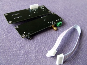
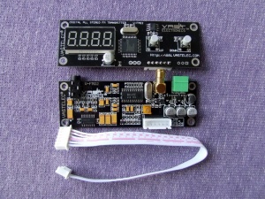
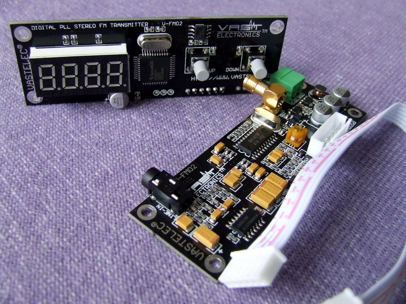
The FM02 is a two board FM transmitter. It accepts a stereo audio source and outputs a stereo FM broadcast signal on the frequency shown on the LED display. It comes just as shown in the picture above.
It is rated at 30mw (that's milli-watts) of transmission power. For most Christmas DIYers this is a nearly perfect amount of power. It will transmit a clear signal for about 2 blocks or 1/4 mile. Why is this good? Because it is illegal in the USA to transmit other then very low amounts of FM radiation without an FCC license.
Skip to this section for more details: [FCC Rules]
The FM02 is not a complete unit ready for use. Instead, it bridges the gap between an out-of-the-box solution, and a build-your-own unit that starts with a bare PCB and a bag of parts.
The FM02 is very small, but packs in a nice set of features.
Key to these is the use of PLL (Phase Locked Loop) technology. PLL keeps the transmitter locked into the designated transmitting frequency without it drifting up or down. This frequency drift WILL occur on other FM transmitters without PLL as the temperature around the unit goes up or down.
The second key feature is the fact that the transmitting frequency is maintained even after power is turned off and back on.
The FM02 is a very sophisticated assembly. Building a unit of this capability and size would be nearly impossible for most DIY'ers.
So, to create a usable FM transmitter, the FM02 needs some help. The builder of the transmitter will take the FM02 and use it as the corner stone of a complete transmitter.
You will need the following items added to your FM02:
- Power. For details, see the POWER section below. 100ma is enough current.
- An Antenna. Never power your unit without an antenna.
- A mounting enclosure. You will need to mount the FM02 boards somewhere safe and dry.
- Connection to a stereo Audio Source. The FM02 has a 3.5mm audio jack.
About VAST Electronics & Product Warranty
VAST warranties the FM02 for two years. The trick with this warranty is that it requires the product to be returned for repair to VAST in China. IF you can catch a group buy in progress on doityourselfchristmas.com, you can also request a replacement when that order is placed with VAST.
You can also receive warranty service from the units purchased directly from www.radiant-holidays (former WLC ventures).
Pictures of FM02's in enclosures
Each FM02 installation is unique !
A gallery of over 25 different installations with pictures and 'how to build notes' is available.
Click Here to see many FM02 installations: FM02_Gallery
Power Requirements
Do NOT power it up without an antenna. You don't need to have your 'real' antenna ready for this. You can put an sma-to-BNC adapter on and then stick a 12" piece of wire into the center of the BNC connector. This will dissipate the RF energy just fine. Just be sure you don't enlarge the hole inside the BNC.
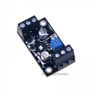
DO NOT apply anything GREATER then REGULATED 9V-16V DC to your unit. 12V DC is the ideal voltage to shoot for. If you aren't sure, then ask for help in the forums. Use a meter to check the voltage first. If all you have is a wall-wart that is labeled 12V, then that is most likely NOT regulated. A simple test of the output voltage with a meter will tell the tale. I use one of the voltage regulators from Sure Electronics with my unit (Part number:PS-SP12113). These are about $5 online.
While the unit will 'run' on the voltages noted above, you should try to run it on 12V. If you operate the unit at a reduced voltage, this only drops the mean voltage feeding the chip and thus drops the chips ability to function correctly. By turning down the operating voltage, (that is one way to reduce that hissing pilot level), but your also reducing the correct operating voltage for not just the FM chip, but the microprocessor, the PLL, the display, the final RF amp, the whole thing, not to mention reduced range and added distortions in the audio paths within the TX and FM chip itself.
A good example of this is taking a portable battery operated radio and put a weak battery in it and hear how distorted and low volume the audio is compared to a fresh correct voltage battery.
You need very little power for an FM02. A power supply rated at only 100ma is sufficient.
When you connect power to the FM02 it is VERY important that you get your positive(+) and your negative(-) correct.
If you hook up the power incorrectly, you can easily damage/ruin the unit.
Do you have a HUM ?
Many folks will experience some HUM in the transmitted audio. This is normal. The good news is that you should be able to eliminate this hum with the use of a Ferrite Bead.
(See Audio Section below for poor audio quality problems)
(See the Ways to improve the sound quality for Advanced Users Section below if you hear a 'shhhhhhhhing' sound)
If you look at the tech that is already in your house, you will see these beads on lots of things. They are in power cords, and even ethernet cables. I get mine for free this way. I just cut them out of these cords. If you work in an office, you can usually go to the cube of the LAN/Networking guys and ask them for an excess power cord with one of these 'bumps' in the cord. They usually have dozens of extras laying around.
As far as size, you want to be able to wrap the wire through the hole and around the perimeter 3 times for maximum effect. You also need to wrap it tightly and secure it in place with a nylon tie wrap. So, it depends on the size of the wire that comes out of your wall wart, you need to have a diameter that can fit three wraps of the wire and the tie.
If you use a Wall Wart for power, you absolutely need a ferrite bead on the power cord coming out of the wall wart.
It is also a good idea to put a bead on the audio cable coming out of the PC.
The beads should be placed on the FM02 end of the cable.
Sometimes, it helps to put a ferrite bead on the audio cable between the PC and transmitter.
NOTE: it never hurts to put one or more ferrite beads on your cables. They may or may not eliminate your HUM, but they never make it worse.
Some Beads split in half, some don't !
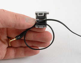
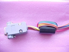
There are some good pictures in the wiki-pedia-:
http://en.wikipedia.org/wiki/Ferrite_bead
Audio
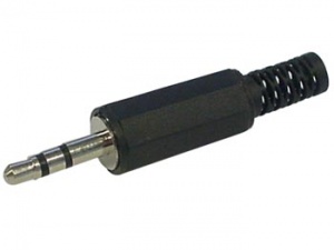
The FM02 has a standard 3.5mm stereo jack for the wire that is carrying your audio signal.
There is one key point about the audio. It works best with a line level audio input. The Audio Out jack on a PC is NOT line level. Line Level is a very low volume level signal. The Volume level on your PC needs to be set very low, barely audible. If you overdrive the audio signal, it will result in a FM transmission that will sound distorted.
.
Schematic and PCB layout

The schematic and PCB layout are documented in a .pdf file.
This document shows the electronic board schematic and the PCB layout for the main transmitter board.
What is not shown is the information for the 'Display' board of this two board set.
[Click Here for the full Schematic & PCB layout File].
Detailed Board Dimensions
Outline of the 'display' board.
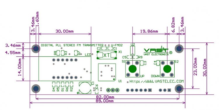
The second board has the same physical outline dimensions. It also lines up with the 4 corner mounting holes.
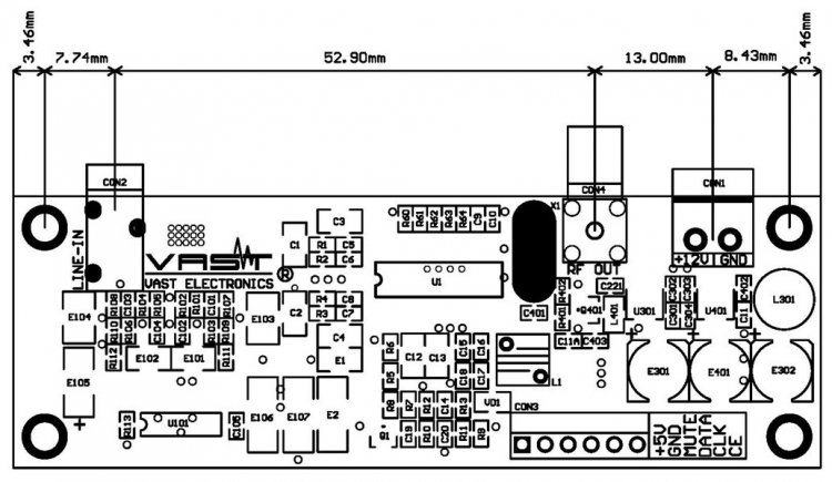
Here is a pdf file that contains a scale outline that will serve as a template for the display board. You would use this to create your own bezel if you want to dress-up your installation: [Bezel Template]
Antenna
The FM02 has an antenna connection that will look a bit unusual to most folks.
It is known as an SMA type of connector.
Reference: Wiki entry for SMA connector
It is important when attaching an antenna/converter/cable to this connector that you do not over-tighten it. The outer part of this connector is a 'press-fit' part. It is possible to simply defeat the resistance of the press fit and cause this part of the connector to fall off! So, if you use a wrench, be very careful, the connector is rated for INCH Pounds of torque.
Most DIY'ers will want to convert this to the BNC type of connector because BNC components are easier to find.
The converter shown below will correctly hook to the FM02. SMA is the smaller gold colored part of the connector. You can purchase the adapters from diyledexpress.com or from ebay.
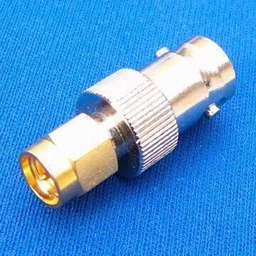
You will need to buy or make an antenna. There are MANY different designs for antennas. A large number of DIYers have made a type of antenna known as a dipole. This is an easy to make antenna that will serve almost anyone's needs. Here is a link to a pdf with instructions to make your own:
How to Make a Dipole Antenna
More recently, DIYC member Jhinkle published a paper for an antenna design that is easier to build with very good transmission characteristics.
Here is the link to a posting on the subject.
DIYC discussion thread
You can go directly to the excellent design and build paper at this link:
pdf paper for a ground plane antenna
What Frequency to Use
This is real simple, go to this website and find a frequency that is unused.
If there are no unused frequency's, then pick one that is not very powerful and
get your radio out and check it out. If you can't pick up any radio stations at your house, odds
are no one will complain when you start broadcasting on that frequency.
NOTE: There are seasonal radio stations. A open frequency in June may be used in December. You should plan accordingly.
Where can I get one of these wonderful FM transmitters ?
NB: Vastelec told U.S. distributors in January 2015 that it would no longer manufacture FM02 transmitters. New old stock and used FM02s may be available.
They are usually stocked at DIYLEDExpress
They are usually stocked at Radiant Holidays.(Was WLC Ventures)
These come up as group buys on the DIYC forum from time to time.
They have also been seen for sale on eBay from seller: Vastelec or user HLLY.
RDS hookup information
This section involves modifying your FM02.
If you do this, you void the warranty.
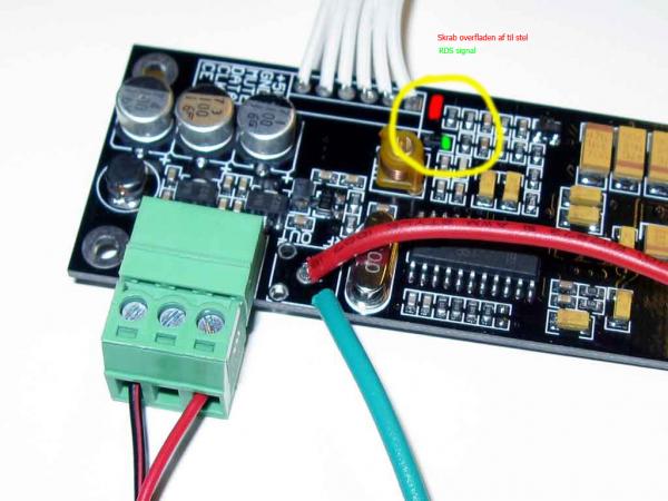
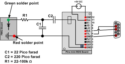
Here is a picture of hooking the pira mini-RDS unit up to an FM02
The green spot on the PCB is the RDS data hookup point.
The red spot is a section of the PCB that was scrapped away revealing the copper. This is used a a soldering point for the ground.
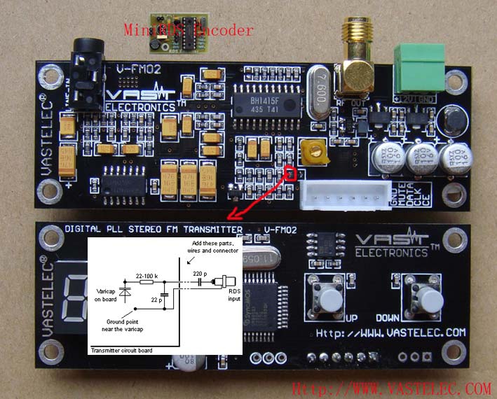
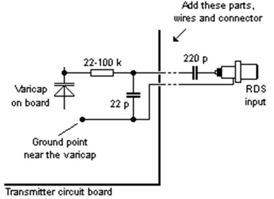
Another View of the GREEN RDS connection spot: Notice, the insert showing the full schematic of the hookup. Two capacitors are needed as noted. (220 picofarad and 22 picofarad) The resistor can be any value within the range noted.
Pira Mini-RDS hookup diagram:
Additional Modifications
This optional modification is noted on the pira mini-RDS datasheet, but not implemented on the mini-RDS board from pira:
You can add a status LED to the mini-RDS board between pin 1 and ground, with a 2.2k Ohm resistor.
It blinks +- once per second when on, and really fast / almost steady on when transmitting RDS data to the transmitter...
.
Why you should care about the transmitting power of your transmitter (FCC regulations)
It's real simple: Do not transmit on a channel that is already in use by a commercial entity that can be heard in your location. The easiest way to do that is to not buy more transmitter then you need.
That is why the FM02 is such a good choice. Below is the official FCC (USA) verbiage discussing low power FM transmissions.
Did you know if you use an FM transmitter the FCC can inspect your transmitter at any time without a search warrant?!! It's true. If the FCC finds you operating equipment that is in violation, you must give them your transmitter so they can destroy it ! If you don't, you will face a large fine. Read through this FCC website discussing the use of an FM transmitter as an 'unlicensed' operator. Click here: FCC information for unlicensed operators
"FCC REGULATIONS FOR THE NON LICENSED OPERATION OR RADIO BROADCASTING"
PART15:
Unlicensed operation on the AM and FM radio broadcast bands is permitted for some extremely low powered devices covered under Part 15 of the FCC's rules. On FM frequencies, these devices are limited to an effective service range of approximately 200 feet (61 meters). See 47 CFR (Code of Federal Regulations) Section 15.239, and the July 24, 1991 Public Notice. On the AM broadcast band, these devices are limited to an effective service range of approximately 200 feet (61 meters). See 47 CFR Sections 15.207, 15.209, 15.219, and 15.221. These devices must accept any interference caused by any other operation, which may further limit the effective service range. For more information on Part 15 devices, please see OET Bulletin No. 63 ("Understanding the FCC Regulations for Low-Power, Non-Licensed Transmitters").
The good folks at RAMSEY have even more detail on their website at: FCC rules information regarding transmitter strength
Ways to improve the sound quality for Advanced Users
Please note: This should be considered an advanced modification. There are hundreds of FM02 in use by the DIYC community and the vast majority use them without this modification.
Some folks want to create the best possible quality sound from their transmitters. It is possible to hear a small 'shhhhhhhhh-ing' sound in the background of the transmitted sound.
The "shhhhh" issue is not a power supply problem, or audio source problem. The problem is the 19Khz pilot level on the BH1415 chip.
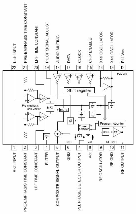
I recommend everyone download the BH1415 data sheet and look at the chip's block diagram and pin layout in order to follow along in solving this "shhhhh" problem.
Pin 19 is the 19Khz pilot tone level. By default, this pin is at a high capacitance state when left open. This pin adjusts the 19Khz pilot level. When it is left unconnected, the pilot level is 30+ percent above the standard 10 percent of modulating the carrier. If the pin is connected to a surface chip cap, this cap may be open or has changed value thus the 19Khz level is still too high.
In order to correct this, a proper modulation monitor or O-scope capable of 100Mhz or more will be needed to adjust properly.
The best capacitor value I have found that brings the 19Khz pilot level down to its standard 10 percent level is a 220pF. The pilot rides at around 11.3 percent. A far cry from the 30+ percent.
Connect the capacitor between Pin 19 of the BH1415 chip and ground.
Do not run your FM02 unit at a reduced voltage to correct this shhhhhhing. This only drops the mean voltage feeding the chip and thus drops the chips ability to function correctly. By turning down the operating voltage, that is one way to reduce that hissing pilot level, but your also reducing the correct operating voltage for not just the FM chip, but the microprocessor, the PLL, the display, the final RF amp, the whole thing, not to mention reduced range and added distortions in the audio paths within the TX and FM chip itself.
A good example of this is taking a portable battery operated radio and put a weak battery in it and hear how distorted and low volume the audio is compared to a fresh correct voltage battery. The same happens to the FM02 when power is reduced to try to solve the hissing. It is not solving it at all, it is merely "covering it up" but it is still there and will always be there until the pilot level is correctly adjusted.
The reason why some transmitters using the BH1415 chip have the hissing is because the pilot is left to run wild so that at further distances the stereo transmission will still be received at those greater distances than it would be when the pilot is adjusted to standard. So moral here is either hassy hissy stereo at a distance, or excellent clean smooth sounding stereo audio within the intended range of these low power devices. I would go with the latter because all that hissing over driven pilot level is also decreasing your carrier power and reducing your range anyway.
Specifics about the Modification
I used a plain ol ceramic disc cap, clipped the leads so they would be short but long enough to allow folding of the capacitor on its side so it rests on the board.
Now on some designs and board layouts, Pin 19 has solder on it, it is soldered to the foil pad on the board, and nothing else. Others have a chip capacitor from Pin 19 to ground, and a few of those have too high a value of capacitor for the proper pilot level.
Solder one lead of the cap to Pin 19 at it's very end to avoid over-heating the pin. Then solder the other end of the capacitor to a nearby ground on the board. If necessary you can run a short wire for the ground connection to the 220pf capacitor.
Use an iron no greater than a 15 watt or over-heating of the pin will result and possibly damage the FM chip.
Also note that the lead of the capacitor that connects to Pin 19 MUST be short as possible. If this lead is too long, it will pick up and inject clock pulse noise onto the pilot carrier. Secure the capacitor with a dab of silicone or putty.
