Configuring Groups: Difference between revisions
No edit summary |
No edit summary |
||
| Line 49: | Line 49: | ||
Figure 1-13<br /> | Figure 1-13<br /> | ||
[[File:Figure_1-13.png]] | [[File:Figure_1-13.png|900px]] | ||
| Line 55: | Line 55: | ||
Figure 1-14<br /> | Figure 1-14<br /> | ||
[[File:Figure_1-14.png]] | [[File:Figure_1-14.png|900px]] | ||
| Line 61: | Line 61: | ||
Figure 1-15<br /> | Figure 1-15<br /> | ||
[[File:Figure_1-15.png]] | [[File:Figure_1-15.png|900px]] | ||
| Line 82: | Line 82: | ||
Figure 1-17<br /> | Figure 1-17<br /> | ||
[[File:Figure 1-17.png]] | [[File:Figure 1-17.png|900px]] | ||
| Line 89: | Line 89: | ||
Figure 1-18<br /> | Figure 1-18<br /> | ||
[[File:Figure 1-18.png]] | [[File:Figure 1-18.png|900px]] | ||
| Line 96: | Line 96: | ||
Figure 1-19<br /> | Figure 1-19<br /> | ||
[[File:Figure 1-19.png]] | [[File:Figure 1-19.png|900px]] | ||
Revision as of 06:09, 21 January 2013
Back to: HLS Getting Started Manual
The next step is to configure output channels into groups.
In this example we will have two trees. Each tree will have 3 output channels. Each tree will be a group.
Groups are very powerful things. For example, our trees might be three colors, we can create a group for each tree and a group that includes all trees, and maybe we would like a group that has only red lights form all of the trees, arches and other lighting elements in our display.
We can also have a group with all of the outputs. Groups make it possible to show and work with a subset of all outputs channels.
Groups are a very powerful tool in HLS.
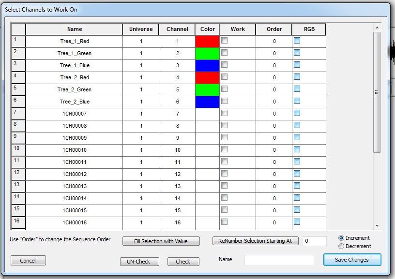
Click on the Manage Channels tab at the top of the page. Next select the choice Select Channels and Assign to Display Group. The screen shown below (Figure 1-10) should appear.
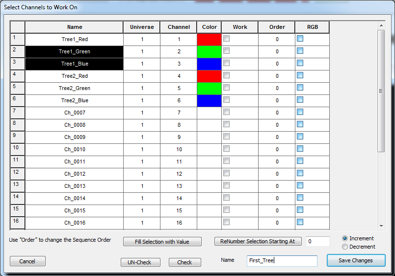
Click the left mouse button down on the first output to be assigned to Tree_1 and move the mouse down to the last one to be included: outputs 1, 2, and 3 in this example.
Note how they are highlighted after they have been chosen.
Next you must click on the Check button on the bottom so that a check appears in the Work column for each output. The last step is to enter a name for the group Name box on the lower right. In this example First_Tree was entered for the group name. Next click on the Save Changes button on the bottom right on the screen. At this point we have created one group consisting of outputs 1, 2, and 3 and assigned them to a group named First_Tree.
Note: you can also choose channels individually to include in a group by manually clicking on the Work check box for each. For example, if you wanted the first, third and fifth output to be included in a group you could individually click on the Work check box for each output to be included and the save them as a group.
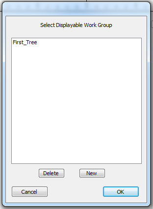
Next we will add more groups. Click on the Manage Channels tab at the top. Choose the Select Channels and Assign to Group selection. This time, because one group was already created, a different style window will appear as shown in Figure 1-11. Note that the First_Tree group is now shown. Choose the New option to add a new group.
Follow the same procedure to create a second group. Use the mouse to select the second three outputs (4, 5, and 6) to create a group named Second_Tree. When you are done, choose Save Changes. At this point we should have 2 groups: First Tree and Second Tree.
Now that we have groups we can begin to program a sequence. We need to choose the group that we would like to work with in the sequence editor.
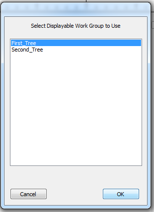
Click on Manage Channels and then Select Group to Work On. The screen shown in Figure 1-12 should appear.
Click on First_Tree as shown and then click on OK.
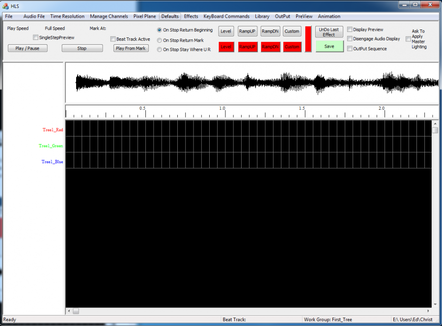
The sequence editor screen will appear (Figure 1-13). Note that it shows the three channels and their assigned color. Note the O-scope view of the WAV file at the top. There are high and low pass filters available to filter the WAV file for the O-scope view at the top of the sequence editor. The high and low pass filters are available in the WAV file tab. To use the filters you could enter new values in the high or low pass filter enable the filter, select OK and the O-scope view will be redrawn to show the new filter that has been applied.
Note also the three channels of 50 ms time divisions to the right of the channels.
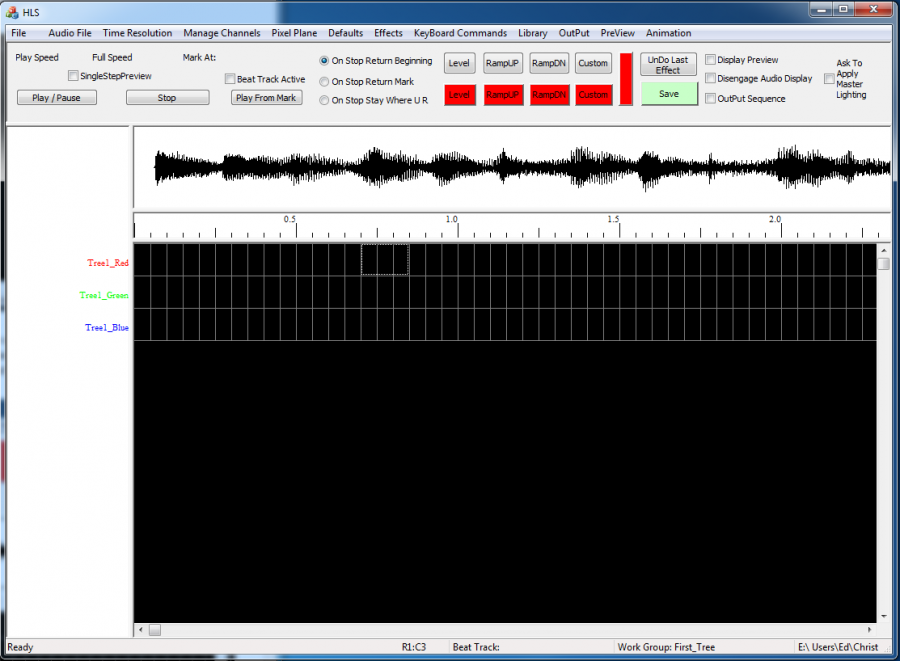
Now we can begin to develop the sequence. To select cells to apply effect to, use the left mouse button and click in the leftmost cell that you want to apply the effect to. You will see a dotted line appear around the cell. The drag your mouse to the right (and down if you want to apply the effect to multiple channels). When you are in the right most cell that you want the effect to apply to, Click the left mouse button once again. You should see all of the cells you chose surrounded by a dotted line (Figure 1-14).
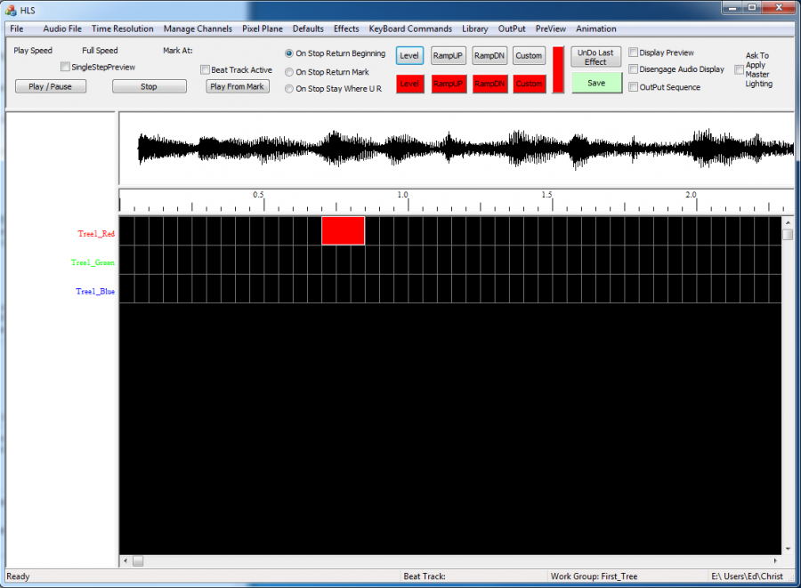
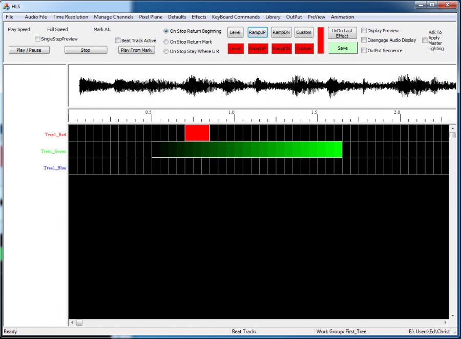
Next you must choose an effect to apply to the cells. The available effects are on the right side of the screen above the O-scope view. Note that there are buttons forLevel, RampUP (U), RampDN (d), and Custom (C). There is also a button to undue the last effect if you make a mistake. In this example the Level effect button was chosen (Figure 1-15). Note that the effect showed up in the color that was configured for this output channel.
Note: if you ever want to cancel the selection you are currently working on you may use the ESC key to cancel the previous selection you are working with. For example, if you ever think the software has hung up while you are adding an effect, it really has not. It is probably waiting for you to apply an effect to selected cells. But you can use the ESC key to cancel the last selection. This is also very useful if you select the wrong cells by mistake and want to redo it. Use the ESC key.
Important Editing Features
Note that if you now click on the right-most cell once in an effect you can expand the number of cells the effect to the right or shrink the number of cells in the effect.
If you click on the left-most cell in the effect once you can move all of the cells in the effect to the right or left.
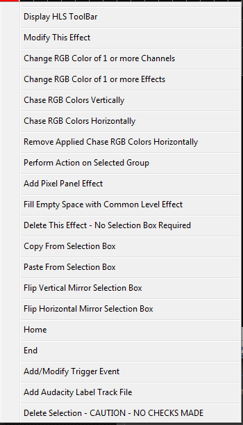
If you right-click on the cells you can modify the effect (Figure 1-16). In this example you can change the cell length of the effect and the intensity level. You also could have changed the type of effect.
Next a ramp up was added in Figure 1-17 for channel 2.
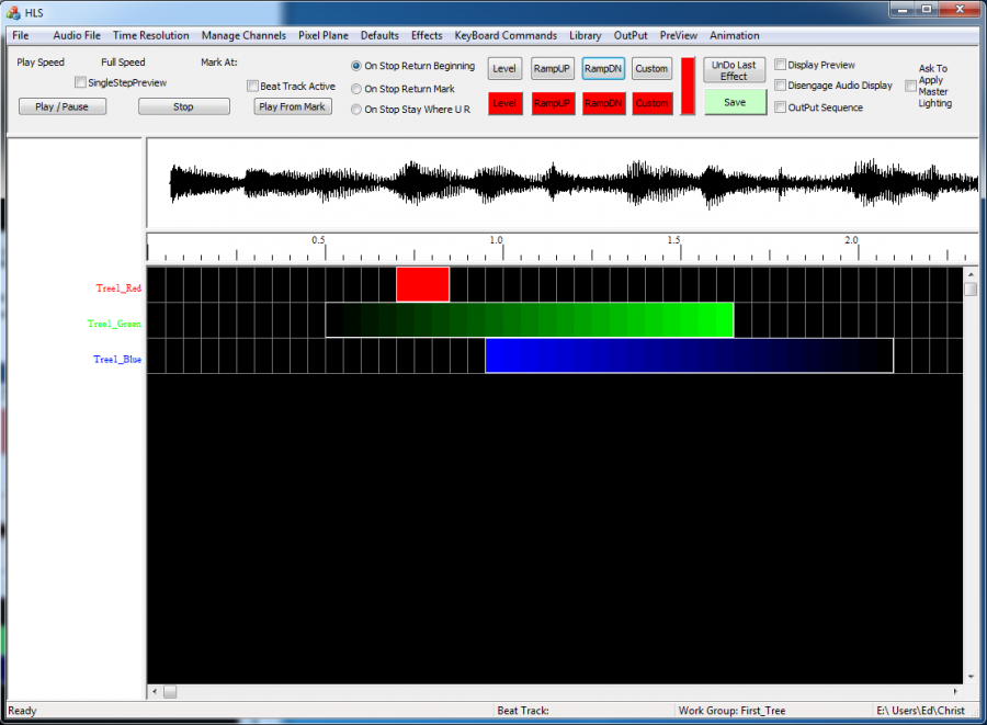
A ramp down was added for channel 3 in Figure 1-18.
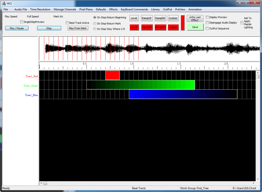
Figure 1-19 shows what happens when the Play button was clicked on (upper left). Note the red vertical lines that appear as the song plays left to right. Note also that we will not see anything happen with the outputs yet because we have not created a sequence preview (simulation) yet.
Helpful hint: If you want to delete an effect, right click on it and then choose modify. You can then change the type of effect or delete the whole effect form the screen.
Review of the Cell Selection Process
A left-click starts the cell selection process. A second left click finalizes the selection of the rectangle.
ESC deletes the selection rectangle and aborts the selection process. To select an effect for copy or anything but move or enlarge – start the selection by Ctrl Left Click on first cell. This tells the system that the operation is a selection Operation (NOT a move operation).
While you are in the selection process (before second left click) you can use the Page UP/Down, or the arrow keys to shift the whole sequence screen up down, left or right.
Note that the selection (cells selected) moves with the sequence. This could be used to move down or up to see more channels or advance to a different point in the song.
To copy the effects enclosed in the selection rectangle – use Ctrl C. To then paste the copied effects - select a single cell (two left clicks to make a single cell selection) – then use Ctrl P.
