VLP SWR Bridge: Difference between revisions
Imbluenote (talk | contribs) |
Imbluenote (talk | contribs) |
||
| Line 53: | Line 53: | ||
(1) http://www.firestik.com/Tech_Docs/Setting_SWR.htm | (1) http://www.firestik.com/Tech_Docs/Setting_SWR.htm | ||
(2) Resistive SWR Bridge by Ian Keyser, http://www.gqrp.org/resistive_swr_bridge.pdf | (2) ARRL Antenna Book, 2007, p. 28-7 | ||
(3) Resistive SWR Bridge by Ian Keyser, http://www.gqrp.org/resistive_swr_bridge.pdf | |||
Revision as of 11:17, 2 May 2014
VLP SWR Bridge
The Very Low Power Standing Wave Ratio, or VLP SWR, Bridge is a tool designed by IdunBenhad for the DIY community. The bridge combined with a DVM or Ammeter will allow the user to "match" the antenna and other environmental variables with the with the transmitter.
What is SWR and how to measure it
SWR (standing wave ratio), is a measurement of how efficiently your antenna system will radiate the power available from your radio. In simple terms, your transmitter would like to radiate all of its power, but can only do so if the other components cooperate. Bad coax and mounts, or inefficient antennas and ground plane can cause system bottlenecks. The easiest way to understand the concept is to think of it in terms of water flow. That is, if you put a one inch faucet on a two inch pipe, your potential output will be restricted by the one inch outlet. So goes antenna systems. Setting your antennas SWR will reduce the restriction of radiated power. (1)
To measure SWR in a RF path or system, a SWR meter or bridge is placed in line and the votage readings are taken. Ideally, a SWR meter should be connected to the line as close as possible to the antenna: All practical transmission lines have a certain amount of loss, which causes the reflected wave to be attenuated as it travels back along the line. Thus, the SWR is highest closest to the load, and only improves as the distance from the load increases. (2)
Briefly, there are two types of SWR bridges. The first type is the design that uses a facsimile of a coax line as the pickup for processing and measuring the forward and reflected power of an antenna. This type requires a more powerful transmitter than the FM01/FM02 or similar types and are therefore not useful for our purposes.
The second is the resistive type SWR bridge/meter. This design is simple and easy to build. It uses low cost resistors and other components to accomplish what is needed to measure the antenna. It is accurate and easy to construct.
Most commercially available SWR meters are designed for higher power transmission systems. IdunBenhad discussed the non-availability of an SWR meter that would respond to “very low power” and said that there were no meters currently available that were usable for the DIYCer. After weeks of research and experimentation, he found and tested a workable solution that is low in cost to build and easy to use.
This meter is named: VERY LOW POWER (VLP) SWR Meter. This meter is not an original design, but was “borrowed” from other experimenters and designers.(3) The resistive meter presents a constant load to the transmitter and the SWR will not be over 2:1 even if the antenna is not connected. This is a safety factor for our transmitters, as THEY SHOULD NEVER BE TURNED ON WITHOUT AN ANTENNA, SWR METER OR SUITABLE LOAD CONNECTED.
VLP SWR Design and Schematic
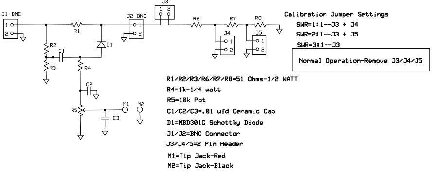
Above is the schematic of the VLP SWR bridge. There are several changes from the original design from Keyser(2). Notably, it has a built-in calibration system consisting of R6-R7-R8 & J3-J4-J5. The diode has been changed from a germanium (1N34a type) to a Schottky diode, which is more sensitive than the original diode and is reversed from the original diagram.
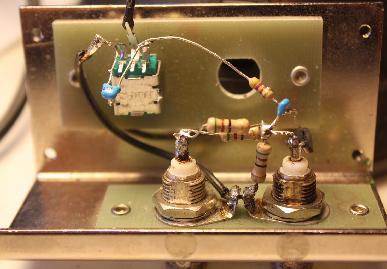
The first attempt at this meter was a breadboard to see if it worked as advertised. Fig. 1 & Fig. 2 show how this was implemented and the meter worked very well. This allowed me to experiment and make changes easily. If the constructor wishes, this meter could easily be built as in the pictures and a PC board not used.
As the experimentation and measurements progressed, I discovered that reversing the diode D1 had an unexplained effect on the readings. If the diode were used as shown in the schematic, meter readings were adequate, even though the readings were negative voltage/current. If the diode were reversed as in the original design, meter readings were not enough to make the instrument useful. I have not been able to explain this phenomenon.
The reversing of diode D1 causes the voltage/current output to be negative, but causes no problems if a DVM is used as it automatically accepts plus or minus voltages. If a microammeter is used, all that has to be done is reverse the positive and negative leads.
The resistors R1-R2-R3-R6-R7-R8 are ½ watt. This means the meter can handle ½ watt of power. As the FM01/02 is only about 30 milliwatts this meter is much more than adequate. It you are using a higher power transmitter, it will handle up to ½ watt or 500 milliwatts.
The main concern in building this meter was the availability of parts and cost. Because most DIYCers already have a DVM or analog VOM, a dedicated microammeter is not included, thus saving that cost. Most DVMs have a low voltage range of 200 Millivolts and this is ideal. Ease of construction and use was kept in mind and to that end a PC board was designed and etched. The “built-in calibrator” has been designed into the board. The calibrator is seldom used but I felt it was necessary to have a readily available source of calibration so the user would be aware of the readings and the actual SWR. The calibration circuitry consists of R6-R7-R8 & J3-J4-J5, a very low-cost addition.
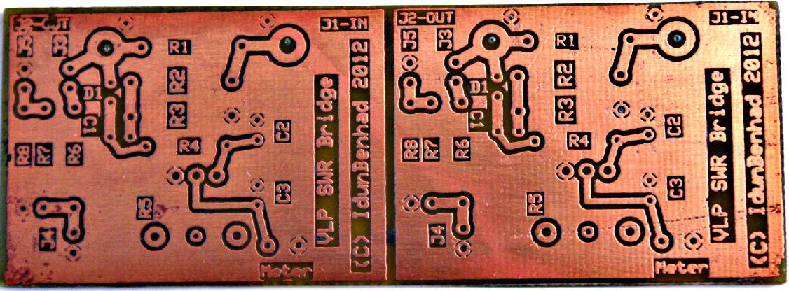
The PC board used can be home-etched and went through several iterations before the layout was final. The PC board in below performs very good and makes a strong unit. Shown in Fig. 3 are 2 boards etched at the same time. I used ExpressPCB to layout the board. The 3.8” x 1.4” board was then cut apart, ending up with two 1.9” x 1.4” boards. The ExpressPCB pattern is in the Coppers section on the DIYC board.
A group buy was also run on this where a production PCB was made. The layout is similar, but slightly smaller to the original.
BOM and Bridge Construction
The construction is slightly unconventional and the assembly instructions should be followed carefully. (
Refernces
(1) http://www.firestik.com/Tech_Docs/Setting_SWR.htm
(2) ARRL Antenna Book, 2007, p. 28-7
(3) Resistive SWR Bridge by Ian Keyser, http://www.gqrp.org/resistive_swr_bridge.pdf


