VLP SWR Bridge
VLP SWR Bridge
The Very Low Power Standing Wave Ratio, or VLP SWR, Bridge is a tool designed by IdunBenhad for the DIY community. The bridge combined with a DVM or Ammeter will allow the user to "match" the antenna and other environmental variables with the with the transmitter.
What is SWR and how to measure it
SWR (standing wave ratio), is a measurement of how efficiently your antenna system will radiate the power available from your radio. In simple terms, your transmitter would like to radiate all of its power, but can only do so if the other components cooperate. Bad coax and mounts, or inefficient antennas and ground plane can cause system bottlenecks. The easiest way to understand the concept is to think of it in terms of water flow. That is, if you put a one inch faucet on a two inch pipe, your potential output will be restricted by the one inch outlet. So goes antenna systems. Setting your antennas SWR will reduce the restriction of radiated power. (1)
To measure SWR in a RF path or system, a SWR meter or bridge is placed in line and the votage readings are taken. Ideally, a SWR meter should be connected to the line as close as possible to the antenna: All practical transmission lines have a certain amount of loss, which causes the reflected wave to be attenuated as it travels back along the line. Thus, the SWR is highest closest to the load, and only improves as the distance from the load increases. (2)
Briefly, there are two types of SWR bridges. The first type is the design that uses a facsimile of a coax line as the pickup for processing and measuring the forward and reflected power of an antenna. This type requires a more powerful transmitter than the FM01/FM02 or similar types and are therefore not useful for our purposes.
The second is the resistive type SWR bridge/meter. This design is simple and easy to build. It uses low cost resistors and other components to accomplish what is needed to measure the antenna. It is accurate and easy to construct.
Most commercially available SWR meters are designed for higher power transmission systems. IdunBenhad discussed the non-availability of an SWR meter that would respond to “very low power” and said that there were no meters currently available that were usable for the DIYCer. After weeks of research and experimentation, he found and tested a workable solution that is low in cost to build and easy to use.
This meter is named: VERY LOW POWER (VLP) SWR Meter. This meter is not an original design, but was “borrowed” from other experimenters and designers.(3) The resistive meter presents a constant load to the transmitter and the SWR will not be over 2:1 even if the antenna is not connected. This is a safety factor for our transmitters, as THEY SHOULD NEVER BE TURNED ON WITHOUT AN ANTENNA, SWR METER OR SUITABLE LOAD CONNECTED.
VLP SWR Design and Schematic
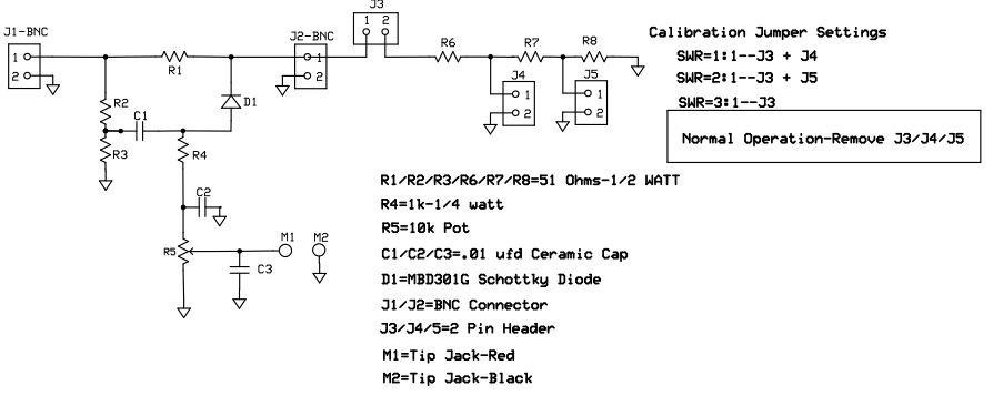
Above is the schematic of the VLP SWR bridge. There are several changes from the original design from Keyser(2). Notably, it has a built-in calibration system consisting of R6-R7-R8 & J3-J4-J5. The diode has been changed from a germanium (1N34a type) to a Schottky diode, which is more sensitive than the original diode and is reversed from the original diagram.
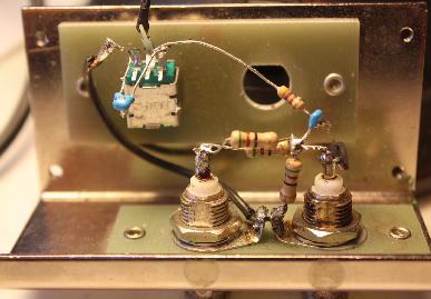
The first attempt at this meter was a breadboard to see if it worked as advertised. Fig. 1 & Fig. 2 show how this was implemented and the meter worked very well. This allowed me to experiment and make changes easily. If the constructor wishes, this meter could easily be built as in the pictures and a PC board not used.
As the experimentation and measurements progressed, I discovered that reversing the diode D1 had an unexplained effect on the readings. If the diode were used as shown in the schematic, meter readings were adequate, even though the readings were negative voltage/current. If the diode were reversed as in the original design, meter readings were not enough to make the instrument useful. I have not been able to explain this phenomenon.
The reversing of diode D1 causes the voltage/current output to be negative, but causes no problems if a DVM is used as it automatically accepts plus or minus voltages. If a microammeter is used, all that has to be done is reverse the positive and negative leads.
The resistors R1-R2-R3-R6-R7-R8 are ½ watt. This means the meter can handle ½ watt of power. As the FM01/02 is only about 30 milliwatts this meter is much more than adequate. It you are using a higher power transmitter, it will handle up to ½ watt or 500 milliwatts.
The main concern in building this meter was the availability of parts and cost. Because most DIYCers already have a DVM or analog VOM, a dedicated microammeter is not included, thus saving that cost. Most DVMs have a low voltage range of 200 Millivolts and this is ideal. Ease of construction and use was kept in mind and to that end a PC board was designed and etched. The “built-in calibrator” has been designed into the board. The calibrator is seldom used but I felt it was necessary to have a readily available source of calibration so the user would be aware of the readings and the actual SWR. The calibration circuitry consists of R6-R7-R8 & J3-J4-J5, a very low-cost addition.
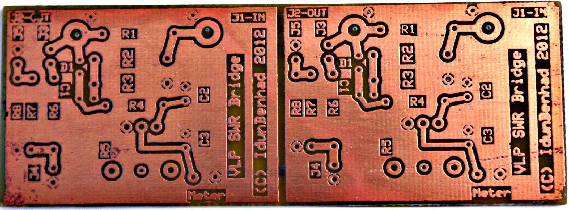
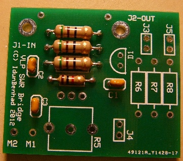
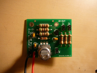
The PC board used can be home-etched and went through several iterations before the layout was final. The PC board in below performs very good and makes a strong unit. Shown in Fig. 3 are 2 boards etched at the same time. I used ExpressPCB to layout the board. The 3.8” x 1.4” board was then cut apart, ending up with two 1.9” x 1.4” boards. The ExpressPCB pattern is in the Coppers section on the DIYC board.
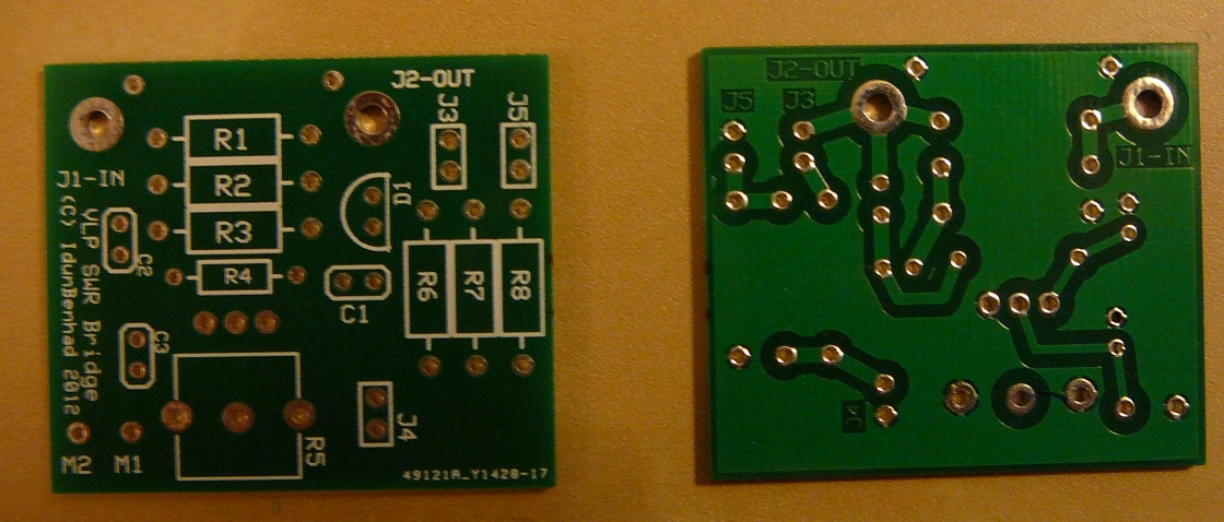
A group buy was also run on this where a production PCB was made. The layout is similar, but the PCB slightly smaller to the original to reduce production costs.
BOM
The construction is slightly unconventional and the assembly instructions should be followed carefully. If you can solder a Renard SS board, and can use a drill then you can make this board without problem.
The Current BOM is below
QTY Part Desc Mouser #
6 R1-R3/R6-R8 Resistor-51 ohms/½ watt Carbon Film 293-51-RC
1 R4 Resistor-1k ohms/1/4 watt Carbon Film 291-1k-RC
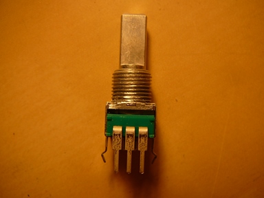
1 R5 Potentiometer-10k—vertical mount 688-RK09L114001T
3 C1-C3 Capacitor-.01 ufd/50v Ceramic 594-K103K15X7RF5TL2 (or alt 21RX410-RC)
1 D1 Schottky Diode 863-MBD301G
2 J1-J2 BNC Panel Connector 571-5-1634523-1 (or atl 523-112575)
1 M1 Tip Jack-Red 530-105-0802-1
1 M2 Tip Jack-Black 530-105-0803-1
1 Knob 6mm D-Shaft 450-4763
3 J3-J4-J5 2 pin header 538-22-03-2021
3 Shunt 2 pin shorting for J3-J4-J5 151-8000-E
1 Enclosure* 616-74923-510-28
- Mouser Part 616-74923-510-28, is what was originally used in the prototype, but there are many different sources. Radio Shack has Part # 270-1805, which is much larger than needed but cheaper than Mouser. Or a cheap alternative is Lowes #72440 plus 70972 (single gang box with metal blank cover), total with tax is under a dollar at this writing.
VLP SWR Bridge Construction
The construction is slightly unconventional and the assembly instructions should be followed carefully. If you can solder a Renard SS board, and can use a drill then you can make this board without problem.
1) Inspect board for any obvious manufacturing defects
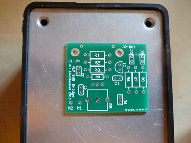
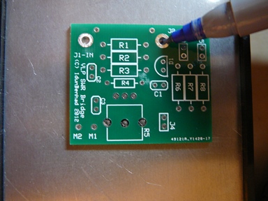
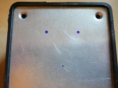
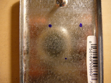
2) Before Soldering any parts, prepare the front panel of your enclosure. You can use the template (File:SWR3a-Front-Panel 1333828358.pdf) or use the PCB to mark the enclosure lid or panel with a fine point sharpie or pencil for the drill positions for the BNC jacks and pot shaft. J1 and J2 are the BNC connectors. The via inside the R5 silk screen is the potentiometer marking location.
If marking the top of the panel make sure you have the top of the PCB (silk screen visible) while marking
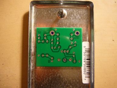
Or If marking the back of the panel make sure you have the bottom of the PCB (silk screen NOT visible) while marking.
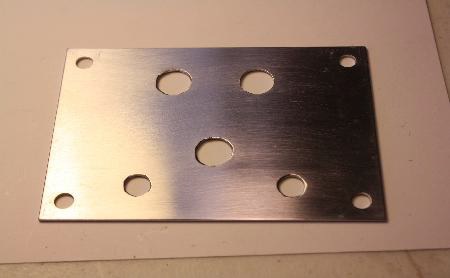
For these three holes you will need to drill with a 3/8" bit.
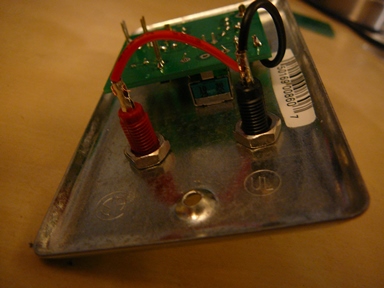
You will also need to mark and drill two holes for the tip jacks. Drill 1/4" for these.
A finished example is below:
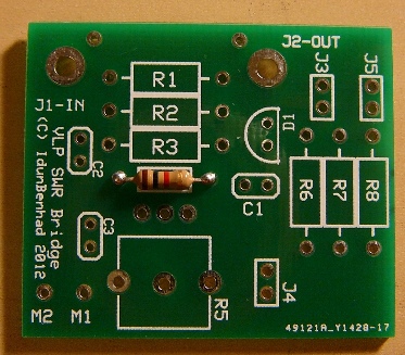
3) Insert R4 (1K-1/4 watt resistor). Part is not polarized and can be installed in either direction.
Solder into place and clip leads. Save these two leads for later use.
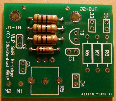
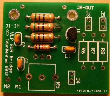
4) Insert R1-R2-R3 (51 ohms-1/2 watt resistor). Part is not polarized and can be installed in either direction.
Solder into place and clip leads. If you forgot to save the leads from step 2, save two of them now.
5) Insert C1-C2-C3 (.01 ufd capacitor). Part is not polarized and can be installed in either direction.
Solder into place and clip leads.
6) Insert D1 (Schottky Diode). Part IS polarized, observe direction and install with flat on diode matching the silk screen.
Solder and clip leads.
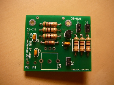
7) Insert R6-R7-R8 (51 ohms-1/2 watt resistor). Part is not polarized and can be installed in either direction.
Solder into place and clip leads. If you forgot to save the leads from step 1 or 2, save two of them now.
Also picture shows header pins already installed, i forgot to take a pic after installing just the resistors, sorry!
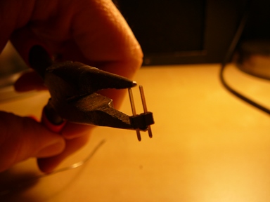
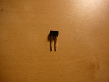
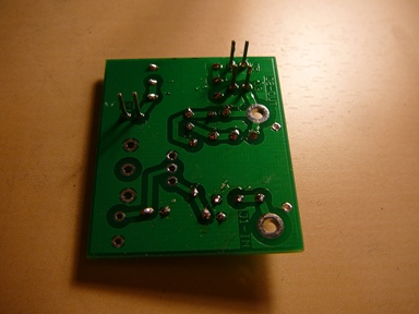
8) Prepare and Install J3-J4-J5 (2 pin headers). The pins of the header are moved in the plastic mount until they are flush. See first two pics below picture below.
Insert part from the front of the board so the pins are sticking out of the back as shown and solder. DO NOT Clip the pins after soldering.
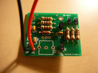
9) Install M1 & M2 wire. Cut a RED and BLACK wire each 2 inches long, strip the ends and tin. Insert the BLACK (M2) wire into the
Ground hole and the RED (M1) wire into the Meter hole coming from the pot. Solder both into place.
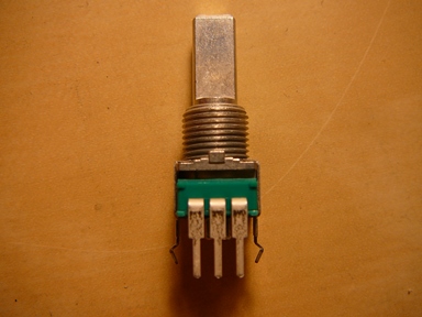
10) Prepare & Install R5 (potentiometer). There is a small tab on the potentiometer that is for alignment purposes, you can notch your panel for this or as it is really not needed file it off.
Place R5 on the board BUT DO NOT SOLDER AT THIS TIME. If your panel holes don't quite line up you may put stress on the solder joints and break them if you solder now.
11) Install BNC connectors and Tip jacks to already drilled front panel. Leave the BNC jack nuts loose enough that they can shift slightly so it can move to align with the PBC.
12) Mount PCB on to front panel. Take the PCB and align with the BNC jacks. Once installed and aligned, put the washer and nut on the potentiometer to hold the PCB in in place to the front panel. BEFORE soldering the BNC connectors finish tightening the nuts. Now solder the BNC connectors (J1 & J2) & the potentiometer (R5)
13) Solder ground tabs on J1 & J2. For the ground tabs on the BNC connectors, bend them up and insert one of the saved resistor leads through the PCB into the solder tab. Bend it so it stays in place and solder the lead to the tab and the lead to the PCB. Repeat for the other jack. Clip leads
14) Solder wires to tip jacks. Strip and tin the end of the wire if you havent already. Insert the red wire in to the red tip jack and black into black. Solder the wires to the tip jacks
15) Calibrate the Meter (DO NOT INSTALL IN THE ENCLOSURE YET!).
Calibration
This SWR Meter requires no power except from the transmitters output.
Again, check the PC board for shorts or solder bridges. Do not mount in box yet.
1) Connect the transmitter to the Input BNC connector J1. DO NOT TURN TRANSMITTER ON UNTIL IT HAS BEEN CONNECTED TO THE SWR METER. DO NOT CONNECT ANTENNA UNTIL INSTRUCTED.
2) Plug a DVM (Digital Voltmeter) into the meter jacks. Set the DVM to 200 Millivolt range. If your meter does not have 200 MV, set to 2 VOLT DC range. A 0-100 microammeter may used in place of a DVM or an analog Volt Ohmmeter may be used. Set the analog meter to measure current on its 50 microamp range, if available. Otherwise use the lowest DC voltage range or lowest current range. For now, the assumption will be a DVM.
3) Turn on the transmitter, setting the frequency to somewhere near the middle of the band, i.e. 98 MHZ. Watch the meter and adjust R5 for a near 200 millivolt reading. If using 2 volt range, adjust R5 for 0.2 volts. The reading is not critical, but should be as close as possible to 199 MV. If 199 MV is exceeded, the DVM will blank, indicating an overrange condition. If using a microammeter, R5 is set to 100 microamps or full scale of the meter.
4) Put a shunt across J3 and observe and record the DVM reading. It should be in the area of 67 MV. This is an SWR of 3:1. (See TABLE on page 12.)
5) Put a shunt across J5, leaving J3 in place. Record the DVM reading. It should be around 30 MV. This is a 2:1 SWR.
6) Remove the shunt on J5 and put it on J4. Leave J3 in place. The DVM should read 00.0 MV. This is a SWR of 1:1.
7) Remove all shunts including J3. The board has now been calibrated and the shunts will no longer be used except to recalibrate in the future.
8) Turn off the transmitter and mount the SWR meter in its box. It is now ready for use.
Using the Meter (i.e. Testing your Antenna)
The SWR meter is simple to use and understand. Basically, we are looking for a minimum reading on our meter, whether it be the DVM, VOM or microammeter.
Connect the transmitter to J1-IN and the antenna to J2-Out. Turn on the transmitter. Set the transmitter frequency near the center of the FM band and start increasing the frequency, going toward 108 Mhz. Observe the meter. It may go up or down, according to where the antenna is resonant. As the resonant frequency is approached, the readings will become smaller, until a minimum reading is reached. This minimum reading may or may not be zero, but should be very low, in the order of 1-3 MV.
If the reading keeps increasing, start back the other way, decreasing the frequency (going toward 88 Mhz) until a minimum reading is obtained. If a very low minimum is not found, then there is probably something wrong with the antenna or feedline. It may be shorted or open or the length is not correct. The user need not be concerned with the actual SWR unless it exceeds the calibrated reading obtained in Step 4 above. Anything above 3:1 SWR is unacceptable for operation and the antenna will have to be changed to get it down. Where 3:1 SWR occurs was determined in the calibration steps. The ultimate goal is to achieve a very low minimum reading. As described above, it is easy to find the frequency at which your antenna is tuned. From this minimum reading and the frequency at which it occurs, we can change our antenna easily to be tuned to the frequency we will be using. Let us say that our desired frequency of operation is 98.7 Mhz. It is at this frequency that we want to have a minimum voltage reading. We have observed and recorded the readings as described above and we find the minimum reading to be at a frequency of 95.3 Mhz. This means the antenna is too long and must be shortened. Carefully cut 1/4” off EACH end of the antenna and make some more readings to see how far the antenna moved in frequency. Having made the antenna shorter, the minimum reading will now be above 95.3 Mhz, say 96.1 Mhz. (96.1 Mhz is an example. The amount of frequency change will be different from this example.) This now gives us a good idea of where and how much the antenna length should be changed. The length should not be changed over 1/2” (1/4” off each leg) at a time, but 1/2” increments used and new readings made each time it is cut. You will observe that the antenna will “step right in” to your desired frequency. Be very careful not to go to far, as the antenna can easily be made too short. From the above, it is easy to see that the opposite is true if the antenna is too short. If it is, solder 1” to 2” to it, making it too long, and “step it in” as the above paragraph explained. It is interesting to note the affects that various objects will have on the antenna. If the antenna is strung between two wooden rafters as mine is, merely walking under the antenna will change its frequency. Also bringing a metal object, such as a rod near the end of the antenna will change it, but moving that rod along the antenna toward the center feedpoint will have less affect. Also, making the antenna into a “V” will change it, sometimes to the better. Putting the antenna in a bush or taped to a wall will also change it. You can easily observe these changes with the VLP SWR meter. I have not mounted the antenna in PVC to see what effects it has on the resonant frequency. This is planned for a future experiment and I will report my findings then. A graph should be made of your antenna and meter readings. 1...Start at 88.0 Mhz, record the meter reading. ( See page 12). 2...Step the frequency to 88.5 Mhz and record the meter reading. 3...Step the frequency up 500 Khz each time and record. 4...Repeat Step 3 until the frequency is 108 Mhz. 5...Enter your meter readings into a graphing program. You can see the actual resonant frequency from this graph. The calibrator included is a simple but effective addition. It works this way: The VLP SWR Meter is designed for 50 ohms impedance. The 3 resistors, R6-R7-R8 are connected in series for a total of 150 ohms which is equivalent to an SWR of 3:1. If R8 is shorted by J5, the series resistance to ground is now 100 ohms resulting in an SWR of 2:1. Removing J5 and shorting R7-R8 with J4 results in a resistance of 50 ohms, a SWR of 1:1 and a zero meter reading. Note that J3 must be in place at all times during the calibration phase. It is removed for normal use. As an aside, if desired, the meter can be made a 75 ohm unit by substituting 75 ohm resistors for R1-R2-R3 & R6-R7- R8. All other factors will remain the same, except now the meter will exactly match a dipoles' impedance. Because of the low difference between 50 and 75 ohms, this is not necessary. As stated before, the SWR using the 50 ohm meter with a 72 ohm antenna will never read a perfect match.
A graph of my antenna is on page 12. This antenna is the one described in “FM02 Transmitter Setup” (3). The resonant frequency is clearly shown in this graph as about 97.6 Mhz. It was originally designed for 101.2, but later used at 98.7 Mhz with excellent results. As is clear from the graph, the antenna is too long, probably because of the mounting in the wooden rafters of “Command Central”, also known as IdunBenhad Lab. (No white coats are worn here however, only white hats.) If the antenna were to be hung “in the clear”, the resonant frequency would change and it is planned to do some further experimenting now that the SWR meter is completed. The VLP SWR Meter should not be left in the line at all times but removed and the antenna connected directly to the transmitter after testing. There is however, an exception to this. If your range is too much, you can cut down the power of the transmitter by leaving the meter in-line. This will reduce the power at the antenna to one fourth that of the transmitter output. The FM02s 30 Mw becomes 7.5 Mw at the antenna connector. This neglects any feedline losses.
Notes & Observations
The VLP SWR Meter does not have to be built in the box listed. I used this because I happen to have some on hand and it is inexpensive and available at Mouser and other suppliers. There is also a version available without the aluminum front panel but there should be a metal front panel, either the aluminum shown or one etched from PC board material as shown in the drawing. The advantage to this is that the various components would be marked. BNC connectors do not have to be used, either. There is room for SO239 through-panel connectors if PL259 coax connectors are being used. If BNC connectors are used and an adapter for SO239 is used on the OUTPUT (J2), disconnect the antenna but leave the adapter on the BNC when setting the full-scale meter reading. After R5 is set, reconnect the antenna. The BNC connectors used in the prototyping were purchased on E:bay (4). The Mouser equivalent part number is shown in the BOM. This is the nearest I could find to the E:bay connectors and has not been tested. The dimensions are slightly different but should be OK. If the constructor can wait for the shipment from China, these parts are well worth the price and you will end up with 18 spares! Different meter readings may be observed when moving your hands around the meter and coax feedlines. Apparently this has to do with grounds, grounding of the shield of the coax and how well it is shielded. As the goal is a minimum reading, this can be ignored. The actual SWR can be interpolated if one is interested. It appears the readings are not entirely linear, as 2:1 SWR was 30 Mv and 3:1 SWR was 66.2 Mv, but it is close enough for calculation. SWR is measured in tenths, 1.0:1, 1.1:1, 2.5:1, etc. The voltage difference between the calibrated readings would be divided by ten and this would arrive at an approximation of the actual SWR. The difference between 1:1 and 2:1 SWR was 36 Mv., thus every 3.6 Mv would be one-tenth SWR. 1.5:1 SWR would be a reading of about 18 Mv. For our purposes, this is probably academic and for the users own information and experimentation. What we are looking for is that minimum reading and getting the antenna tuned to our frequency, so it is not necessary to know the actual SWR. The knob used was modified. I ordered the wrong one and the shaft size was not big enough. By drilling out the shaft hole carefully to 15/64” (one size below 1/4”), the knob fit tightly and securely. There are of course, many alternatives to the knob used. That can be the users choice. Caution: When connecting the antenna to J2-OUT, it is easy to bump the knob, changing the reference setting. By placing a rubber grommet on the shaft below the knob, sliding the knob down to touch it with some pressure, it will have resistance and be harder to move. There is a wealth of information available on the internet about resistive SWR Bridges/Meters. Do a search for “Resistive SWR Bridge” and get ready to do some reading and learning. (9) The power output of my FM02 varies across its' frequency range of 88-108 Mhz. It puts out more power at the ends of the range and falls off slightly in the center which means the reference voltage is changing as the frequency is changed. If these readings are recorded, starting at 88 Mhz and going to 108, a reference table of the power output is established. This table can be used in the future if it is felt the power output of the transmitter has changed. Because the power output varies across the band, the reference will probably have changed, but this is of no real concern unless you want absolute accurate readings when setting up your antenna. There will be no real difference between the first procedure, but you can do the following; 1...Run the initial readings with the antenna connected as outlined on pages 7 & 8. 2...Having found the frequency at which your antenna is resonant, remove the antenna and adjust the reference voltage to near 200 Mv at that frequency. 3...Make the adjustments to the antenna, again as outlined on pages 7 & 8.
Refernces
(1) http://www.firestik.com/Tech_Docs/Setting_SWR.htm
(2) ARRL Antenna Book, 2007, p. 28-7
(3) Resistive SWR Bridge by Ian Keyser, http://www.gqrp.org/resistive_swr_bridge.pdf
(4) VLP SWR Meter by IdunBenHad, http://doityourselfchristmas.com/forums/showthread.php?20173-VLP-SWR-Meter
