TIR Destiny CG Commercial LED Flood Light: Difference between revisions
| Line 210: | Line 210: | ||
[http://wayback.archive.org/web/*/tirsys.com* Internet Archive Listing of old TIR Systems Web Pages]<br/> | [http://wayback.archive.org/web/*/tirsys.com* Internet Archive Listing of old TIR Systems Web Pages]<br/> | ||
==Software== | ==Software== | ||
[http://web.archive.org/web/20060516144022/http://www.tirsys.com/products/controls/Designer_May_2005.exe ControlFx Software]<br/> | ===Light Management=== | ||
[http://web.archive.org/web/20060516144022/http://www.tirsys.com/products/controls/Designer_May_2005.exe ControlFx Software: Used to sequence and program light functions]<br/> | |||
===Light Initilization=== | |||
[http://doityourselfchristmas.com/forums/attachment.php?attachmentid=15027&d=1345741540 Initializer User Guide]<br/> | [http://doityourselfchristmas.com/forums/attachment.php?attachmentid=15027&d=1345741540 Initializer User Guide]<br/> | ||
[http://doityourselfchristmas.com/forums/attachment.php?attachmentid=15028&d=1345741579 CFX Initializer Quickstart Guide]<br/> | [http://doityourselfchristmas.com/forums/attachment.php?attachmentid=15028&d=1345741579 CFX Initializer Quickstart Guide]<br/> | ||
[http://doityourselfchristmas.com/forums/attachment.php?attachmentid=15029&d=1345741602 Initilizer Director Setup Guide]<br/> | [http://doityourselfchristmas.com/forums/attachment.php?attachmentid=15029&d=1345741602 Initilizer Director Setup Guide]<br/> | ||
===Light Design and Emulation=== | |||
[http://web.archive.org/web/20060516143653/http://www.tirsys.com/forms/Destiny%20Wizard%20Installer10.exe Destiny Wizard: Used to emulate light output]<br/> | |||
=TIR Flood Discussion Threads= | =TIR Flood Discussion Threads= | ||
Revision as of 18:01, 23 August 2012
TIR Destiny CG Commercial LED Flood Light
Disclaimers
The standard disclaimers pertaining to the information contained on this wiki page are listed here.
THIS PAGE IS UNDER CONSTRUCTION AND IS NOT COMPLETE AND NOT HAS BEEN CHECKED FOR ERRORS YET!!
What is the TIR Flood?
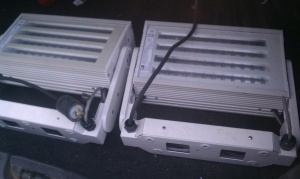
These are commercial RGB outdoor DMX floodlights designed and sold by TIR. They are Model Number: Destiny CG-WGO-RGB-CUS-V2 These lights were originally mounted on the Duke Energy Building and were replaced with other RGB fixtures. DIYC member rfallatt arranged to buy the lights from the building and offered them to users via a group buy in August 2012. There was a mixture of working and bad units sold. The bad units suffered from water entering either the control module or the power supply. TIR Systems (in Canada) were considered the leader in outdoor LED systems and were also popular with large dance halls. They were a public stock company until 2007 when Phillips purchased them.
Manufacturer's Description
- Effective grazing illumination up to 30' with smooth gradient
- Effective projector flood light up to 30'
- Available with narrow or wide asymmetric optics
- Uniform color mixing with 48 Luxeon® LEDs
- DMX512 compatibility for dynamic color control
- TIR® Thermal management system protects electronic components from heat damage
- Robust construction suitable for outdoor applications
- Operational and environmental benefits of LED technology
How does the TIR Flood work?
These are RGB flood lights that are controlled via DMX and possibly via an unidentified ethernet based protocol. There is a 5 pin XLR DMX connector that comes configured for DMX input only. Out of the box these units respond to DMX channels 1-3 (RGB) when powered up and connected to a signal source. These units will fall back to a test sequence if the DMX signal is not applied. The test sequence is a series of color fades. The units also come with a ethernet cable attached and the control protocol has not been established for using it.
Dimensions of the TIR Flood
Full Fixture (with all connectors) H 14.5 X W 16.5 X 5.5 and ~26 lbs
TIR Flood Components
Connectors
The units come equipped with a 15A 125vAC 3 Pin Twistlock power plug, a RJ45 ethernet interface cable and a 5 PIN XLR DMX cable attached. The power and DMX cable come out of the base of the mounting bracket thru the waterproof cable holders. The ethernet cable is tucked inside the base of the mounting bracket and has a rubber waterproof sleeve on the end.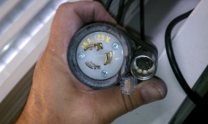
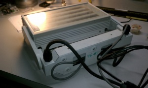
Housing
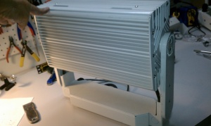
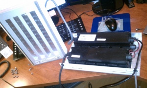
The main housing has the sealed LED Assembly attached to the front and has an internal compartment on the back that is open to the environment that houses the waterproof Control Module and the waterproof Power Supply.
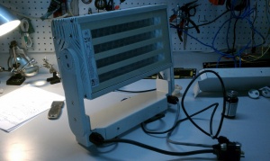
LED Assembly
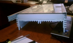
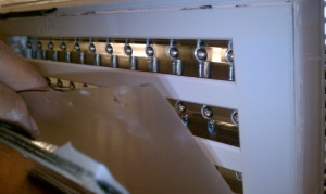
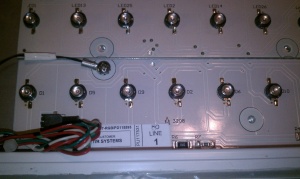
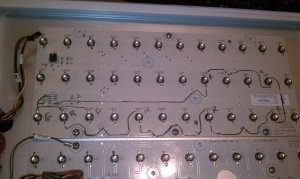
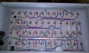
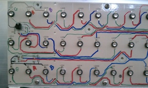
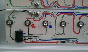
The flood lights have 48 Luxeon LEDs mounted in a sealed module on the front of the unit. There are 16 each of Red, Blue and Green. The LEDs are mounted on two PCB boards. The LEDs are arranged in a 2x6 array for each color on the upper PCB and 1x4 on the lower PCB. This video shows how to test the LED Assembly when removed from the housing.
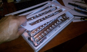
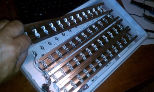
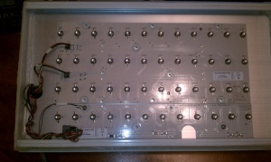
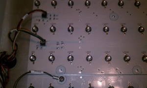
Control Module
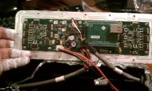
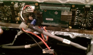
There is a control module that drives the LEDs and responds to the DMX commands provided to it thru the DMX interface. The Control Module is mounted inside a waterproof housing and is attached to the rear heatsink with a generous amount of heatsink compound. Inside of the Control Module there are some HEXFETs that appear to be driving the LEDs (IRL510S). There's a LM2676 5V regulator nearby some of these.
The only large chip on the board is on the backside - has a LDT logo on it, with a LD71D1048C designation.
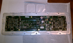
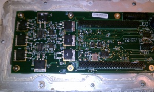
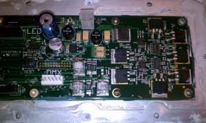
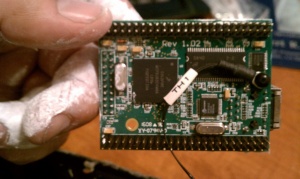
Ethernet Module
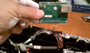
There is an ethernet module mounted inside the control module. The interface to this module has not been identified yet. Technical Information about the Netburner ethernet module. The NetBurner module uses the ColdFire MCF5282 processor. Using the Netburner IP program, one user got the following response "MOD5282 Unit: at 192.168.1.47 running :LuminaireFX (3081041) $Date: 2005/02/04 18:42:48 $, $Name: B_Dma6Aug2004_MainTest $".
Power Supply
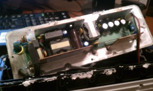
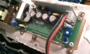
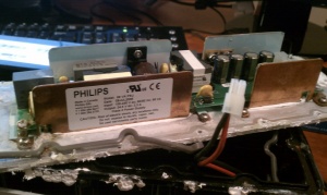
The power supply is a 100-240 VAC input and 24.5VDC 3.3A output. The power supply is sealed in a waterproof enclosure and the wires come through the enclosure via waterproof sealing glands.
The power supply has an input power cord on one end and has a red and black 16ga wire on the other end that connects to the control housing. Midway between the power supply and the control housing there is black shrink wrap on the red and black power leads. If you carefully remove the heat shrink, you will find blue "bullet" type connectors that can be separated by pulling them apart.
Mounting Bracket
The unit comes with a mounting bracket that is adjustable.
Disassembling the TIR Flood
Main Body Separation
- Remove the 3 screws near the rounded back edge on both side panels near the bracket attachment.
- Remove the 2 screws near the rounded back edge on the other two side panels above the heatsink.
- Lift the rounded rear panel off to expose the Control and Power Supply Modules.
Removing the Power Supply or Control Module
- Loosen the Waterproof plastic nuts on the wires entering on both sides of the module to allow the wire to slide through it when you remove the plastic housing.
- Loosen the four screws that hold the black plastic housing and base plate to the light housing. Wear gloves, there is a lot of thermal heat sink compound behind the base plate.
- Turn the module over and remove the screws that hold the base plate to the black plastic housing.
- Gently pry the black plastic housing from the base plate with a flat edge screwdriver, it is held in place by a sealant/gasket.
TIR Flood Power Requirements
The units come equipped with a 15A 125vAC 3 Pin Twistlock power plug. At 100% brightness RGB the flood draws 78 watts @116.5vAC. The internal power supply provides 24vdc @ 3.3A to the control electronics. A quick test of the current of the Red LEDs shows to be about 760-780 mA when full on.
AC Power Cable
| Conductor | Wire Color |
| Line | Brown |
| Neutral | Blue |
| Ground | Green/Yellow |
Controlling the TIR Flood
The flood comes equipped with a 5 pin XLR DMX connector. Only the input wires are connected to the XLR connector, but the output wires are also available and they can be soldered to the plug. The lights can be controlled by sending a DMX signal to the lights on channels 1-3 to control the RGB lights. It is believed that these floods were controlled by a software package called LuminaireFX. This is the Control software developed by TIR for this unit. It's a control system for their "TBus" option.
DMX Wire / XLR Connector
| Signal | Wire Color | XLR Pin |
| DMX IN Shield | Red Foil | 1 |
| DMX IN + | Red Wire in Red Foil | 3 |
| DMX IN - | Black Wire in Red Foil | 2 |
| DMX OUT Shield | Green Foil | NC |
| DMX OUT + | Red Wire in Green Foil | NC |
| DMX OUT - | Black Wire in Green Foil | NC |
Schematic
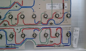
TBD. The following photos show the highlighted traces on the LED PCBs by LED color.
Internal Wiring Color Codes
There is a cable going from the LED panel to the controller, and is grey and marked "LED". It's close to a 25 pin cable, but only 14 wires go to the LED panel.
Convention is that the first color is the full wire color, and the second/third colors are the stripe or dash of color printed on the wire.
Lower LED board (4 LEDs per color)
| LED Connection | Wire Color |
| Common (+) | Red/Green |
| RED | Red/Black |
| GREEN | White/Black |
| BLUE | Green/Black |
Upper LED board (6 LEDs per color)
Upper section
| LED Connection | Wire Color |
| Common (+) | Black/Red |
| RED | White |
| GREEN | Black |
| BLUE | Red |
Lower section
| LED Connection | Wire Color |
| Common (+) | Orange/Red |
| RED | Orange |
| GREEN | Green |
| BLUE | Blue |
Thermistor
There is a thermistor attached to a screw on the LED panel. Leads from this are White/Red and Blue/Red
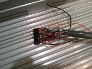
LED Connector
This is the connector marked LED that goes into the controller board. It's a 24 pin dual header. Haven't gotten the measurements yet, but here's the wire connection. Pin 1 is upper left corner as if the connector is plugged into the board. Pin 13 is below pin 1, and closest to the tabs/keys that stick out of the bottom of the connector. Wires are coming up at the viewer. I need to draw a picture, but hopefully that will give folks a good idea.
| Pin Number | Wire Color |
| 1 | White |
| 2 | Green |
| 3 | Blue |
| 4 | Red/Black |
| 5 | Orange/Black |
| 6 | Black/White |
| 7 | Green/White |
| 8 | Black/Red |
| 9 | Orange/Red |
| 10 | Red/Green |
| 11 | Black/Red/White |
| 12 | Red/Black/White |
| 13 | Black |
| 14 | Red |
| 15 | Orange |
| 16 | White/Black |
| 17 | Green/Black |
| 18 | Blue/Black |
| 19 | Red/White |
| 20 | Blue/White |
| 21 | White/Red |
| 22 | Blue/Red |
| 23 | Thermistor \ |
| 24 | Thermistor / attached to Netburner module |
The wires appear to match up, in that the common positive for the 3 sections are pins 8, 9 and 10. Upper LED connections are 1, 13 and 14. Middle LED connections are 2, 3 and 15. Lower LED connections are 4, 16, 17.
Replacement Power Supplies
Non-OEM Replacement Power supplies are available from Ray Wu and DIYLEDEXPRESS.COM
Replacement Control Modules
Non-OEM replacement for the Control Module options include a DCSSR driven by a controller such as the REN48LSD, Simple Renard 32 or the REN64. The REN48LSD and the Simple Renard RGB+W CAN NOT drive these lights directly due to the high current demand per channel (~0.75A), you must use a DCSSR.
Other Information
- Another Hint: These units may have been controlled by "ControlFX Initializer Software", a Windows®XP application to set DMX addresses of the luminaires using the ControlFX Initializer hardware interface. ControlFX Initializer Device The DMX 512A standard comprises 255 “alternate START codes”. The START code is the first byte of data transmitted across a DMX network. TIR Systems has registered START code 37 (hex) for its exclusive use. ControlFX TM Initializer Device refers to a piece of hardware produced by TIR Systems that is used to initialize its luminaires using START code 37. Only TIR®luminaires should recognize data sent with a start code of 37.
- US Patent 7394210 is a TIR Patent on controlling DMX lights.
- The control module essentially performs four functions:
- Read incoming DMX512 packets;
- Read the thermistor for temperature derating;
- Cycle through various color effects; and
- Drive the digital-to-analog converters.
- The DMX512 code produced by the SelectFX controller was non-standard, with a non-NULL packet header designed to communicate color effect and timer synchronization information to the Destiny controller.
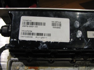
- The units all have a unique serial number that is listed on the label on the front face plate as well as a standalone sticker on the control module. It looks like: 308-0911. This number will be necessary for programming the lights.
DMX Address Translation Board
Since these light responds to DMX Channels 1-3 out of the box, a board is under development to respond to any DMX address and translate it to channels 1-3 to drive these floods. For more info look here.
Documentation
Quick Start Product Guide
Wiring Schematic
Destiny CG Datasheet
Internet Archive Listing of old TIR Systems Web Pages
Software
Light Management
ControlFx Software: Used to sequence and program light functions
Light Initilization
Initializer User Guide
CFX Initializer Quickstart Guide
Initilizer Director Setup Guide
Light Design and Emulation
Destiny Wizard: Used to emulate light output
TIR Flood Discussion Threads
Initial Thread
Flood Fixer DMX Address Translation board
TIR Breakout board
Initializer Software
Video
Test Pattern
Outdoor Test
Another outdoor test
Other Photos
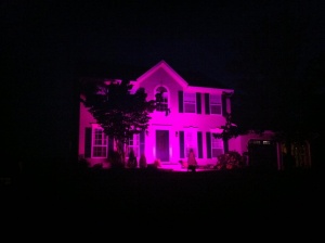
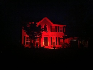
A single TIR Flood lighting a house about 15 feet from the front door, pointed slightly upward.
FAQ
TBD
