Pops-O-Matic ESP Programmer
What is the Pops-O-Matic ESP Programmer ?
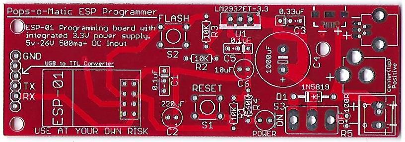
The Pops-O-Matic is a dedicated programming board for the popular ESP-01 module.
This board was inspired from two articles on allaboutcircuits.com. Specifically:
Voltage Regulator
ESP Flashing Circuit
This programming board supplies both the regulated power and the programming interface for the ESP-01 module.
It specifically isolates the ESP-01 from any of the positive power that may be supplied by your serial-to-TTL programmer.
Only Ground, Transmit, and Receive are connected from the external serial-to-TTL programmer to the Pops-O-Matic.
The purpose of this is twofold.
1. To protect the ESP-01 module from voltages over 3.3V.
2. To provide the ESP-01 with well regulated and steady power during the programming sequence.
Pops-O-Matic Overview
The Pop-O-Matic is designed to be flexible in assembly and use.
It can take a wide variation of power input voltages (5V-25V) and can support up to 5 different power connections.
The board is designed to use any of the following for a power input connection:
1. 5mm Terminal Block
2. 3.5mm Terminal Block
3. Micro USB
4. Mini USB
5. Barrel Terminal Jack
The board has a power ON/OFF switch with a power ON LED indicator.
Order a boards
Contact ukewarrior via a PM on DIYC as he often has boards in stock, cheap !
Disclaimers
USE the ESPixel Pops board at Your Own Risk !
The ESPixel Pops board has NO warranty expressed or implied
BOM - Bill of Materials
The BOM contains these generically described parts:
- One ESP8266-01, this is not so much a part, but a complete subassembly.
- D1 - One diode. This must be: 1N4148
- ESP-01 - One female socket header, 2 rows of pins, 4 pins in each row. This functions as the socket where you plug the ESP8266 module into
- One six pin header. Readily available 2.54mm (.1") pitch. (distance between the pins)
- One tactile switch. 6mm x 6mm. Also readily available. These often have choices as to the height of the push button.
- R1 & R2 - Two 1/8W or 1/4W carbon film or metal film resistors. 330 Ohms.
- C2 - One polarized Electrolytic capacitor. Any value from 10uF to 220uF will do. 10V or above. Pay special attention to the diameter and spacing of the leads. The diameter can be no more than 5mm and the leads should be spaced at 2mm.
- C1 - One MLCC monolithic capacitor. 2.54mm lead spacing. 0.1uF, any voltage over 24V. (Usually these are 50V rated) These are typically the 'yellow blob' style capacitors, verses the ones that are shaped like a flat disk. These do NOT have a + & - indication, unlike the electrolitic capacitor noted above.
- U1 - One 3.3v voltage regulator. This must be: LD1117V33, which has a TO-220 style package.
- IC1 - One 5.0v voltage regulator. This part is optional and should only be installed if you are planning to drive 12v pixels.
- Q1 - One Mosfet. This must be: 2N7000 or ZVN3306A, which has a T0-92-3 style package
- A five pin screw terminal header. 5 positions total. This connection should have 3.81mm spacing of the mounting pins.
The ESPixel Pops Tiny board has the same BOM but you omit:
- D1 - One diode. This must be: 1N4148
- One tactile switch. 6mm x 6mm.
- One six pin header. Readily available 2.54mm (.1") pitch.
One of the DIYC members, beeiilll, constructed BOMs for three vendors.
They are contained in the thread:
Click Here:
Within that thread, you can find the BOMs in these posts:
The BOM's are:
Mouser BOM is in Post #35
Arrow BOM is in Post #48
Digikey BOM is in Post #49
Construction Information
The ESPixel Pops is a pretty easy build. The real trick is deciding how you plan to power your pixels as that will affect what you do with the board wiring.
Depending on your power source, this determines if you should install the 5V regulator or just put a jumper in its place as noted on the the board.
The board has a main voltage regulator that provides 3.3V of power to run the ESP8266 module.
This module does not care if you are running 5V or 12V pixels. So, you can connect 5V or 12V to the board.
The board has a place for a second voltage regulator. This is to accommodate 12V pixels.
This is location IC1 on the board. This is a spot for either a 5V regulator or a wire jumper.
To summarize the population of the voltage regulators and ICs:
The pard labeled: U1 is always installed.
The part labeled: Q1 is always installed.
The part labeled: IC1 is installed if you are running 12V Pixel strings
The part labeled: IC1 is NOT installed if you are running 5V Pixel strings AND you must place a jumper in its place as noted on the board.
Click Here to see the schematic:
Wiring The ESPixel Pops
A Key Point Regarding Power
The power supply you use must match the voltage requirement of your pixels.
So, if you run 5V pixels, you must have a 5V PS. Same is true for 12V pixels.
If you accidentally use a 12V power supply on 5V pixels, you will damage your pixels, perhaps to the extent of destroying the entire string.
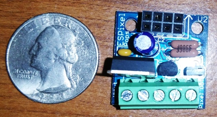
Along the bottom of the board are 5 connection points. (as viewed from the top...)
The two on the left are for input power.
The three on the right are for pixel connection.
You can either solder on a terminal block or directly solder your wires to the board, or do a mix !
The Terminal block has 3.81mm hole spacing. (The more common 5mm terminal blocks would have made the board too wide)
One thing you have to decide is if you will power your pixels through the ESPixel Stick or directly to the Pixel string. (sometimes referenced as "power injection")
It is possible to use the ESPixel Pops as an interface for just the data and run power to the pixels separately.
This is a decision of personal preference and the fact the PCB traces can only handle so much power.
Trial and error is your best approach.
Programming the ESP-01 Module
The heart and soul of the pixel stick variants is the firmware that runs on the the ESP-01 module. Work has been done to consolidate to one common set of code.
Shelby Merrick is the keeper (and key cook & bottle washer) of this code. He keeps the current release of code on his github page. You can find that here: Pixel Stick Software
As of 10/30/2017, the current release was version: 3.0
For Shelby's v3.0 release, there is a Java Flash Tool that you run, enter your SSID and PSK for your wireless network, Pixel, the correct COM port and Upload.
Here is a posting by PCpackrat that describes his experience: NOTE: the most current info is at the github webpage noted below...
this can also be found at this DIYC posting #122 in this thread: Info Thread
The firmware is here: https://github.com/forkineye/ESPixelStick
Read through the README.md dont skim like I did. There is a part (gulp) that requires java to 'zip' up the web site information. I just did that part in linux and then copied the files into the data/www folder in the ESPixelStick folder.
Install the prerequisites in README.md
Pay careful attention to the Arduino for ESP8288 version (2.40-rc1). You will have to choose this branch for download.
My short and dirty TL;DR and things I missed:
Modify ssid and passphrase at the top of ESPixelStick.ino
Under Tools: Choose your board as Generic ESP8266 Module Flash Size should be 1M (128K SPIFFS) CPU Frequency 160 MHz Upload Speed 115200
Power the unit with the button pressed
Upload the firmware
Remove power from the unit and replug again with the button pressed.
Go to Tools and then ESP8266 Sketch data upload (serial monitor has to be closed for this)
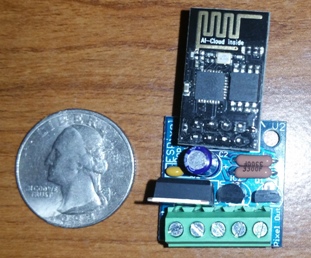
Pictures of built Pixel Pops boards
user kev in California uses Snapple bottles to build a water resistant enclosure for 5 cents
![]()
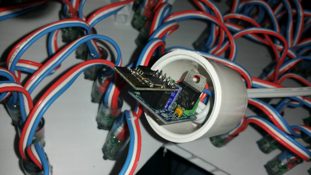
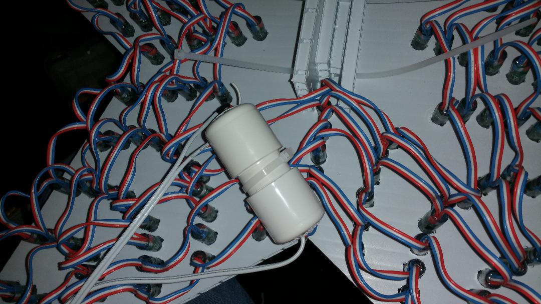
Steven Dill uses a Pixel Pops Tiny board enclosed in 1" thin wall PCV to control the coro star on a mega tree.
