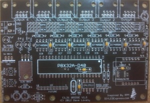
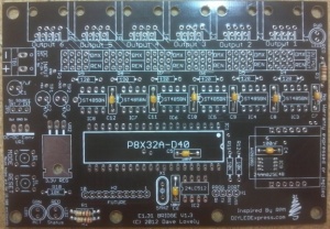
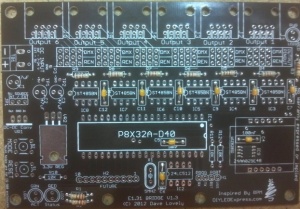
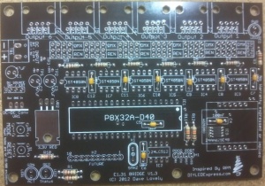
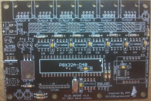
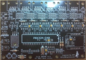
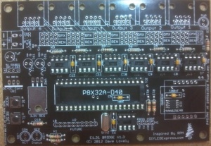
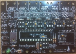
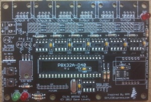
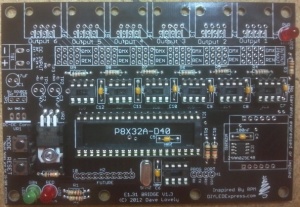
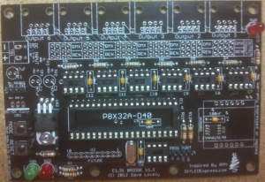
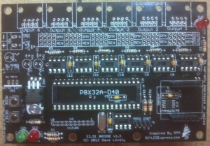
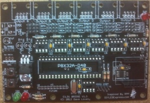
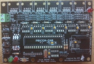
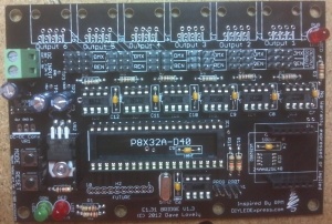
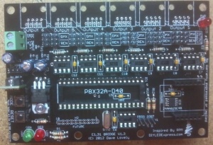
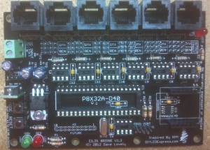
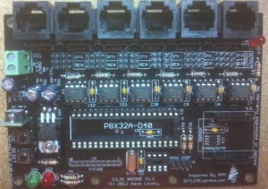
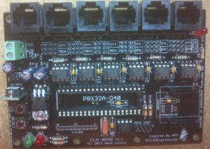
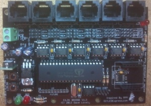
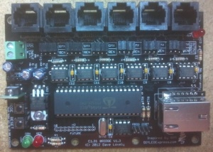
E1.31 Bridge
This is a work in progress!!!!
Disclaimers
The standard disclaimers pertaining to the information contained on this wiki page are listed here.
THIS WIKI PAGE IS NOT COMPLETE YET AND HAS NOT BEEN CHECKED FOR ERRORS.
6 Port E1.31 Bridge Construction Manual
What is the 6 Port E1.31 Bridge?
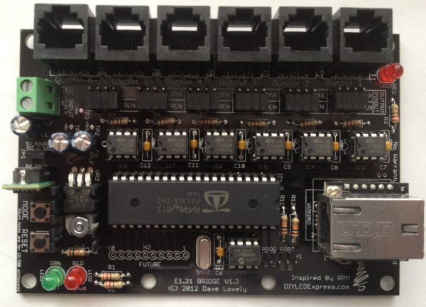
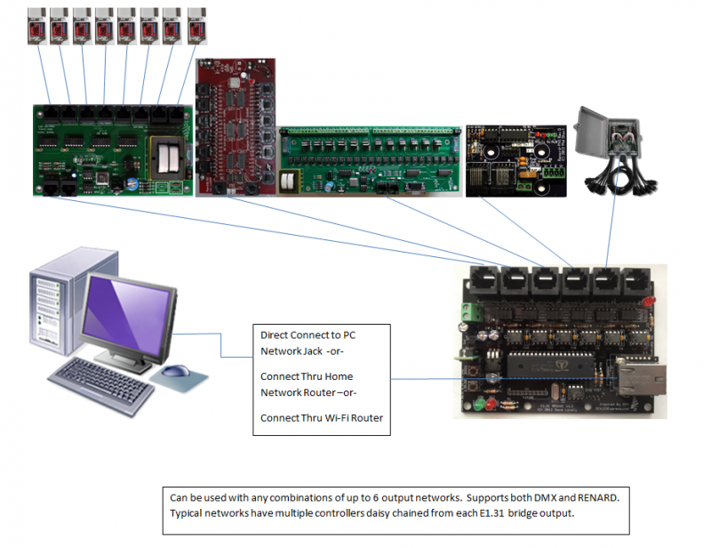
The 6-port E1.31 bridge is a device that allows your PC to communicate with a large number of Renard or DMX controllers using regular Ethernet network connections. It replaces multiple DMX or RS485 dongles with one configurable device that can be mounted in an enclosure in the yard and only requires one Ethernet Cat5 cable (or WIFI) back to your pc or home network. It allows up to 6 DMX universes or Renard networks to be easily controlled from your sequencing software with a minimum amount of wire from your show pc to your controllers. The bridge works with all Renard, DMX and LOR (using DMX) controllers.
The 6-port E1.31 bridge is a device that takes in an E1.31 stream from your network and converts (or 'bridges') that to multiple DMX or Renard output streams. E1.31 or sACN (Streaming Architecture for Control Networks) is a method of multiplexing multiple DMX streams over your network using unicast or multicast UDP packets. The 6-port bridge currently only supports multicast streams. This makes it simpler to configure but has drawbacks in very large configurations (10's of streams). E1.31 can support 63,999 DMX streams or 'universes' (64000->65536 are reserved) so it has a virtually unlimited amount of expansion available.
The 6-port bridge can handle up to six E1.31 universes, each of which get directed to a particular port. By default the bridge is configured to send universe '1' to port number 1, universe '2' to port number 2 and so on but you can assign any of the 64k universe numbers to any port if you wish. The bridge takes in the particular universe stream and either outputs it directly out each port for DMX output or it performs a conversion to Renard protocol. The protocol used depends of course on what you plan to use for controllers on the ports that you have configured. You can configure any mix of DMX and Renard protocols to any port.
The bridge has another feature so that each physical output can be re-wired to support either a "standard" DMX RJ-45 electrical output or a Renard electrical output without resorting to making custom cables to support either. The output of the bridge is always RS-485 in either case. Note that regardless if your Renard controller is running standard Renard/Serial code or Renard/DMX code, the jumpers should always be configured for Renard since the physical interface does not change.
How does the 6 Port E1.31 Bridge work?
As mentioned above, the bridge takes in a multicast E1.31 UDP stream, determines which stream belongs to which port (if any) and sends that data out the appropriate port. The E1.31 stream enters the bridge via an Ethernet port on the Wiz820io module and is converted to a serial signal that is sent on to the Propeller microcontroller chip. Your sequencer or streaming tool sends multicast packets with an address of 239.255.<UHB>.<ULB> where UHB is the Universe high byte and LHB is the Universe low byte. As an example, the address for universe '1' would be 239.255.0.1. This is why using multicast addressing can be simpler to configure since this address is always the same for any device using that universe. The disadvantage of using multicast is that the packets are sent to every device on the subnet regardless if they are destined for it or not. This means the receiving device must read in the header for each packet or have the means to block these within hardware. Depending on the device and the number of universes of data sent it can swamp the device and possibly end up causing a loss of data. Note however that this is not an issue for most networks until you get into the dozens of universes so it's not an issue for most users.
Unicast is another method of sending E1.31 packets. For this method, the IP address used to manage/configure the device is also used for the data packets. In this case, the packets are sent directly to the device instead of being broadcast across the entire subnet.
The Parallax Propeller microcontroller determines if the address matches one of the configured ports universe numbers and if it does, reads in the entire DMX stream and sends them out that particular port either as-is or after conversion to Renard protocol. The Propeller chip is quite powerful, it is essentially eight separate microcontrollers in a single package. These internal processors or COGs as they are called can each run completely different (or the same) code. This allows you to partition different functions to different COGs within your code. If a COG is not used, it does not use any resources which allows you to run the others faster. For more information on the Propeller, visit the Parallax site.
For the bridge, the COGs are used to support both the multiple input processing as well as the six port output processing.
E1.31 Networking Basics and Setup
For more information about how E1.31 works and how you wire up the IP networking side of an E1.31 Network look at E1.31 Protocol
Revision History
6 Port E1.31 Bridge Parts
To build the E1.31 Bridge, you need 4 things:
- The PCB
- The parts to solder on the board, also known as a BOM (Bill Of Materials).
- A power supply to power the board. The board can use any 5-24VDC power supply.
- An enclosure to mount the finished board in. Commonly used enclosures include the CG-500, CG-1000 or the CG-2000 which are available from several vendors
The BOM parts needed to build the board are:
| Mouser BOM | |||
| Part ID | Mouser PN | Description | Qty |
| R1-R3 | 291-220-RC | Carbon Film Resistors - Through Hole 220ohms 0.05 | 3 |
| R4-R9 | 291-120-RC | Carbon Film Resistors - Through Hole 120ohms 0.05 | 6 |
| R10-R12 | 291-10K-RC | Carbon Film Resistors - Through Hole 10Kohms 0.05 | 3 |
| C1-C3 | 140-REA470M1VBK0611P | Aluminum Electrolytic Capacitors - Leaded 35V 47uF 20% 6.3x11mm | 3 |
| C4-C12 | 581-SA105E104MAR | Multilayer Ceramic Capacitors MLCC - Leaded 50volts 0.1uF 20% Z5U | 9 |
| IC1 | 619-P8X32A-D40 | 32-bit Microcontrollers - MCU DIP pkg Propeller Chip | 1 |
| IC2 | 579-24LC512-I/P | EEPROM 64kx8 - 2.5V | 1 |
| IC3-IC8 | 511-ST485BN | Buffers & Line Drivers Hi-Spd Lo Pwr Trans | 6 |
| IC9 | 579-24AA025E48-I/SN | EEPROM 2K 256 X 8 1.8V SERIAL EE, IND | 1 |
| X1 | 520-HCU500-20X | Crystals 5MHz 20pF | 1 |
| Wiznet | 950-WIZ820IO | Ethernet Modules W5200 & MAG JACK ioPLATFORM MODULE | 1 |
| LED1 | 604-WP7113GD | 604-WP7113GD | 1 |
| LED2-LED3 | 604-WP7113ID | Standard LEDs - Through Hole HI EFF RED DIFFUSED | 2 |
| VR1 | 580-OKI78SR5/1.5W36C | DC/DC Converters 7.5W 24Vin 5Vout1 1.5A SIP Non-Iso | 1 |
| VR2 | 511-LF33CV | Low Dropout Regulators - LDO 3.3V 0.5A Positive | 1 |
| Heatsink | 532-577202B00 | Heat Sinks TO-220 HORIZ/VERT SLIM CHANNEL STYLE | 1 |
| S1-S2 | 653-B3F-1000 | Tactile Switches 6X6 Flat 4.3mm Btn Force 100g w/o Grd | 2 |
| IC Socket 1 | 575-199640 | IC & Component Sockets 40P TIN PIN TIN CONT | 1 |
| IC Socket 2 - IC Socket 8 | 575-1104331610003000 | IC & Component Sockets 8P DIP SOCKET SOCKETS | 7 |
| JP1 | 571-826629-3 | Headers & Wire Housings 3P SINGLE ROW | 1 |
| H1 | 571-826629-4 | Headers & Wire Housings 4P SINGLE ROW | 1 |
| Wiznet 1x6 Header | 517-9601066202AR | Headers & Wire Housings 6P STR SR BDMNT SKT 3.0MM TAIL/7.1MMBODY | 2 |
| 2x3 Output Selector | 855-M20-9980345 | Headers & Wire Housings 03+03 DIL VERTICAL PIN HEADER GOLD HT | 12 |
| TB1 | 571-2828372 | Fixed Terminal Blocks 5.08MM PCB MOUNT 2P | 1 |
| J1-J6 | 571-5556416-1 | 571-5556416-1 | 6 |
| Output Shunts | 517-9691020000DA | Headers & Wire Housings 2.54MM SHUNT | 25 |
You can buy the parts directly from Mouser: Click here for Mouser Direct Project BOM
or
The BOM is also available at a discount in a kit that includes the PCB from DIYLEDExpress.com
Building the 6 Port E1.31 Bridge
The 6 Port E1.31 Bridge requires a fair bit of soldering so take your time and ensure you install the components in the correct orientation when required. Start by sorting the components by type and values. Look over the PCB before starting noting the location of the various components. Follow the standard procedure of installing the lowest profile parts first and ending up with the tallest. You can click on any photo to see a larger version of the image.
- □ Begin by inspecting the PCBs to look for any defects such as cracks or breaks. The holes on the board should be open on both sides. Then inspect and sort out the various parts for the boards.
- □ Install the MAC IC, this is the only surface mount IC. It is optional if you are not comfortable with soldering surface mount ICs. The firmware will generate a random MAC ID if the IC is not installed. The IC is polarized and the IC must be installed so that the dot on the package aligns with the dot on the pcb, the lower right side of the pad. For hints on how to solder a SMT device look here.
- □ Install the nine 0.1uF (100nF) capacitors C4-C12. The capacitors are not polarized and can be mounted either way.
- □ Install the three 220 Ohm resistors (red, red, brown, gold) R1-R3. The resistors are not polarized and can be mounted either way.
- □ Install the six 120 Ohm resistors (brown, red, brown, gold) R4-R9. The resistors are not polarized and can be mounted either way.
- □ Install the three 10K Ohm resistors (brown, black, orange, gold) R10-R12 The resistors are not polarized and can be mounted either way.
- □ Install the 5Mhz Crystal X1. The crystal is not polarized and can be mounted either way.
- □ Install the two push button switches S1-S2. The switches are polarized and will only fit on the board one way.
- □ Install the seven 8 pin IC sockets. The sockets are polarized and have a notch on one end. It should be mounted so that the notch is oriented to the left and matching the marking on the pcb.
- □ Install the one 40 pin socket. The sockets are polarized and have a notch on one end. It should be mounted so that the notch is oriented to the right and matching the marking on the pcb.
- □ Install the green ACT LED (LED1). Note that the LED is polarized and the long lead should face towards the top of the board. Note: silkscreen shows "FLAT" side of the LED, this can also be used to check for proper orientation
- □ Install the two red STATUS and POWER LEDs (LED2-LED3). Note that the LED is polarized and the long lead should face towards the top of the board. Note: silkscreen shows "FLAT" side of the LED, this can also be used to check for proper orientation
- □ Install the 3.3V Regulator VR2 with the heat sink. The voltage regulator is polarized and goes only one way. Gently bend the leads of the regulator at the location on the leads where it changes size down at a 90 degree angle towards the flat side of the regulator. Apply thermal grease to the flat heat sink side of the regulator and the heatsink and fasten it to the pcb using a #4 screw and nut.
- □ Install the 3 Pin headers JP1. The short end of the header is soldered to the pcb.
- □ Install the 4 Pin headers H1. The short end of the header is soldered to the pcb.
- □ Install the two WizNet 1x6 pin headers.
- □ Install the twelve 2x3 output selector pin headers. The short end of the headers are soldered to the pcb.
- □ Install the power terminal block TB1. Install so that the wire openings face the edge of the pcb.
- □ Install the three 47uF Capacitors C1-C3. The capacitors are polarized and can only be installed one way. The side of the capacitor will have a stripe on the negative side. The long lead is the positive side, and it goes in the hole marked with a + to the right.
- □ Install the DC-DC Converter VR1. The voltage regulator is polarized and must only be installed one way. The flat side of the voltage regulator must be mounted towards the bottom of the board, aligning with the stripe on the pcb.
- □ Install the six RJ45 jacks J1-J6. The jacks are polarized and they have to be installed with the correct orientation. Gently install all 8 pins into the holes and them firmly press down on the socket to seat the plastic pins in the holes in the PCB.
- □ Install the six RT485BN in IC3-IC8 with the notches facing the left edge with the power terminal block.
- □ Install the EEPROM in IC2 with the notch facing the left edge with the power terminal block.
- □ Install the Propeller in IC1 with the notch facing the WizNet adapter to the right.
- □ Install the WizNet adapter with the RJ45 socket facing the Propeller IC.
H2 will be unpopulated as it is for future expansion.
Congratulations! That completes the construction of the 6 Port E1.31 Bridge!
Jumpers
There are two types of jumper groups on the E1.31 bridge. The first is to set the input voltage and the others to set the desired DMX or Renard physical output.
Power Jumper - JP1
This jumper is used if you are supplying either a well regulated +5v or unregulated +7-24v. If you apply +5vdc to the terminal block, you should put the jumper on the "EXT" setting (indicating you are getting 5v externally). If you apply +7-24vdc, you should put the jumper on the "INT" setting (indicating you are getting 5v internally via the 5v regulator).
You MUST ensure you have this jumper set correctly if you are using voltages greater than 5v as it may (and probably will) cause permanent damage to some components on the board. The Propeller chip uses 3.3v and would be fine but the RS-485 transceivers are 5v devices and would be probably be damaged.
Output Configuration Jumpers
Each port has a set of four separate jumpers. These jumpers set the wiring configuration on their respective output jacks. If you want a DMX wiring output, you need to put all four jumpers to the "DMX" side. If you want a Renard wiring output, you need to put all four jumpers to the "REN" side. It is important that all four jumpers are in the same position for that port. Note that the protocol for the port is different than the wired output. You must set the DMX or Renard output protocol via the Bridge configuration settings.
| Output Jumper Settings | ||
| Pin # | RJ45 Connectors | |
| REN | DMX | |
|---|---|---|
| 1 | SIGNAL GND | RS-485 DATA+ |
| 2 | SIGNAL GND | RS-485 DATA- |
| 3 | NC | NC |
| 4 | RS-485 DATA- | NC |
| 5 | RS-485 DATA+ | NC |
| 6 | NC | NC |
| 7 | NC | SIGNAL GND |
| 8 | NC | NC |
You can use the bridge to drive LOR controllers capable of supporting DMX as well. The simplest method is to configure the software protocol for DMX and use the REN output jumper settings. You will be required build a jumper cable to swap pins 4 and 5 between the two ends of the jumper because LOR has these signals swapped. You may also want to connect pin 6 from the LOR to pins 1 or 2 if using the REN output.
Powering the E1.31 Bridge
As mentioned above, the bridge can be powered with either a well regulated +5vdc supply or an unregulated/regulated +7-24vdc supply. The power supply should supply at least XXX mA (dlovely to supply). Configure the power jumper appropriately before applying power.
Initial Testing
Power up LED Activity
On initial power up the green ACT and the red STATUS LEDs flash a sequence of codes to help identify the status and configuration of the bridge. After they go thru their startup flash sequence, the the green ACT LED flashes when ever it sees IP data traffic and the red LED stays lit to signify that the configuration webpage is accessible. The Green ACT LED startup flash pattern are:
| Green ACT LED Startup Flash Count | |
| # of Flashes | |
| IP Status | |
|---|---|
| 1 | The default bridge IP address mode is DHCP and the bridge acquired an IP address from a DHCP server. |
| 2 | The default bridge IP address mode is STATIC and the STATIC address programmed into the bridge is being used. |
| 3 | The default bridge IP address mode has been overridden due to a button press and the bridge has acquired an IP address from a DHCP server. |
| 4 | The default bridge IP address mode has been overridden due to a button press and the STATIC address programmed into the bridge is being used. |
| 5 | The default bridge IP address mode is DHCP and has been overridden due to no response from the DHCP server and the IP address of 169.254.74.73 is being used. |
| 7 | The default bridge IP address mode has been overridden due to a button press and the IP address of 169.254.74.73 is being used due to the lack of response from a DHCP server. |
Programming the EEPROM
The EEPROM ships from DIYLedexpress with the firmware installed. If you buy the parts from another vendor, or you want to update the firmware to a later version, you must have a PropPlug programming tool.
The current version of the firmware is v2.06 and you can download it here.
The Programming port on the Bridge is the 4 pin header near the WizNet adapter. Match up the silk screen labels with those on the Prop Plug. You will need to externally power the bridge when programming it.
Programming Tools Required
The Propeller processor uses a different programming interface then the usual PICKIT2 or PICKIT3 device used to program the Renard PICS with their firmware. You can not use a PICKIT 2 or PICKIT3 to load the E1.31 bridge firmware. The recommended way to load the firmware in the E1.31 bridge is to use the PropPlug.
PropPlug
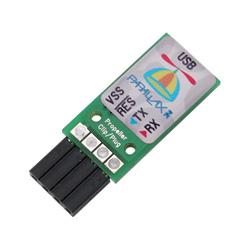
You can buy a PropPlug from DIYLEDExpress during Pre-Sales or find it at Parallax or Mouser anytime.
Build your own Programming Interface
If you do not have access to a PropPlug, but you do have a PC with a true serial port, it is possible to build a simple interface to program the E1.31 bridge using simple common parts you can find from many vendors. However, the low cost PropPlug with it's USB interface works best on most modern computers.
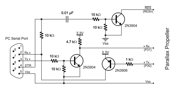
How To Install the Firmware Programming
- Download the Parallax Propeller Tool and install it.
- Run the Propeller Tool application and it will ask of you want to associate .eeprom files with the application, Say Yes.
- You can close the Propeller Tool application and double click on the .eeprom file you downloaded or from within the application go to File->Open and change the 'Files of type' to 'Propeller Applications' and open the Bridge_v2.02.eeprom file.
- A 'Object Info' screen will open, if not already enabled click 'Show Hex'
- Connect the PropPlug to the PC and the PCB making sure that the plug is oriented correctly to match the markings on the pcb.
- Program the EEPROM on the Bridge by selecting 'Load EEPROM' and you are done.
Configuring and installing the E1.31 Driver
In order to use your E1.31 Bridge, you must install and configure the software on your pc to allow your sequencing software to speak E1.31 protocol to the bridge. Click on the following links for instructions for:
Configuring the E1.31 Bridge
Once the bridge has been built and passed preliminary tests, it must be configured to operate. The configuration can be done when the bridge is connected directly to the PC or to the home network. The configuration page can be accessed via the default IP address of the controller via the browser of your choice. The default IP address of the bridge is 192.168.1.206 Open up your browser and enter http://192.168.1.206 and the setup page for the bridge will appear in the browser. If you have changed the default IP address of the bridge, you must use that address to access the setup screen.
IP Address Configuration
The default IP address and mode of the bridge when initially setup is 192.168.1.206 and is a static IP address. This can be later changed thru the web interface to what ever network address you need. Note that all E1.31 bridges and the E682 Pixel controller all use this default IP address, so if you have multiple devices on the same network, you must change the static address of the units to avoid a conflict.
Temporary Manual Address Overide
When you are troubleshooting the E1,31 bridge, it is possible to force the IP address of the unit to use another setting by using the MODE and RESET buttons at power up. If you press the MODE and RESET buttons at the same time and hold down the MODE button while you release the RESET button you can temporarily change the IP address mode. You must release the MODE button after the correct number of flashes listed below to activate that mode.
| Green ACT LED Overide Flash Count | |
| # of Flashes | |
| Temporary Overide IP Status | |
|---|---|
| 1 | No Change. |
| 2 | The last saved STATIC IP address is enabled |
| 3 | DHCP IP address is enabled. |
Configuration Commands
Once you access the E1.31 webpage you can configure the device settings via a command line interface (original firmware) or via a webpage drop down menu (beta firmware). In the command line interface, all commands are entered on the command line and are temporary until saved. It is critical to follow all command line changes with the "SAVE 0" command to ensure your updates are saved in the device. You must then reboot the E1.31 bridge to make the changes take effect by either hitting the RESET button, or entering "BOOT 999" .
Save
SAve n where n is a memory page number from 0 to 7. Writes the currently displayed configuration to the specified memory page
Load
LOad n where n is a memory page number, 0-7. Loads the specified memory page and displays the information on the web page.
Boot
BOot 999 will restart the system. Make sure you do a SAVE first if you have made any changes or your changes will be lost!
IP
IP a.b.c.d where a.b.c.d is any valid IPv4 address.
This should be set within the same subnet as your sequencer PC Ethernet port unless you have routing enabled (not recommended). It is recommended that you have your show network on a separate subnet from your regular home network. This ensures you will not have issues with either interfering with the other. Note that this address is only used to configure/monitor the bridge - it is not used for the sequencer data itself.
Subnet
SUbnet a.b.c.d or SUbnet n where a.b.c.d is any valid subnet mask value, or n is the size of the subnet in bits.
This should also match the subnet mask of your PC Ethernet port since it is normally on the same subnet. This is typically 255.255.255.0 or 24 bits.
Gateway
GAteway a.b.c.d where a.b.c.d is any valid internet address. Usually the address of your router.
DNS
DNs a.b.c.d where a.b.c.d is any valid internet address. Usually the address of your router.
If you are only using DHCP (not recommended), you can leave the static IP areas unused.
Network addressing (static or DHCP IP) is only needed to access the configuration
page with a web browser. Once configured, no IP address is needed for normal operation.
The Default IP Mode, Web Server Mode, No Data Timeout, and Test Pattern commands affect
what happens when the system starts up.
Default
DEfault n where n is 0 or 1.
DE 0 sets the addressing mode to a static or fixed IPv4 network address that is configured with the commands above. DE 1 sets the addressing mode to DHCP - you must have a working DHCP server on your network for the bridge to get an address. It is highly recommended to use a static IP address for the bridge so that you always know where to find it on the network.
Universe
UNiverse b n Where b is the RJ45 output jack number, from 1 to 6 and n is universe from 1 to 63999.
Protocol
The Protocol command is used to set the protocol for each of the six output RJ45 jacks. The current valid protocols are DMX and RENARD.
PRotocol b n Where b is the RJ45 output jack number, from 1 to 6 and n is 1 for DMX protocol and 2 is for Renard protocol.
Baud
The Baud command is used to set the baud rate for each of the four output RJ45 jacks.
NOTE: This command is only used for the Renard protocol. Baud rate will not be displayed when
the DMX protocol is selected.
BAud b n Where b is the RJ45 output jack number, from 1 to 6
and n is 1 for a baud rate of 57,600 or 2 is for a baud rate of 115,200.
The Renard protocol refresh rate at 57,600bps for 512 channels is approximately 90ms and at
115,200bps the refresh rate for 512 channels is approximately 45ms.
The DMX protocol refresh rate is preset to 25ms.
Mode
"MOde" n Where n is 0 for Multicast or 1 for Unicast
TroubleShooting
So - you've built your new 6 Port E1.31 Bridge, connected it up to your computer and tried a quick sequence and nothing happens! There are several checks to perform in order:
Visual Inspection
The very first step involves a close visual inspection of the board. Double check that you have the correct component in the correct location and in the correct orientation. Look at every single solder connection and if some are not shiny or look suspect - reflow them to be sure.
Power
Measure the voltage supplied to the bridge and ensure it's either +5vdc or +7-24vdc and ensure the power jumper is set correctly. Measure the voltage with the supply plugged in and connected to the bridge to ensure it's not shorting out. If the voltage is correct then you know the input level is correct.
Remove any/all socketed chips from the board before proceeding.
If you are using the +5vdc option (EXT), you need to make some measurements of the 3.3v regulator or VR2.
Measure the input voltage between pins 1 and 2 - it should measure 5v (same as the input) - if it isn't then reflow the terminal block, 3.3v regulator and power jumper and check again.
Measure the output voltage between pins 3 and 2 - it should measure 3.3v - if it is much above 3.3v, it's likely the regulator is bad. If it is close to 0v, you may have a short somewhere on the board. Inspect the traces coming from pin 3 over the board and look for solder bridges. If you cannot find a short, then you may have to replace the 3.3v regulator.
If you are using the +7-24vdc option (INT), you need to make some measurements of the 5.0v regulator or VR1.
Measure the input voltage between pins 1 and 2 - it should measure 7-24v (same as the input) - if it isn't then reflow the terminal block, 5.0v regulator and power jumper and check again.
Measure the output voltage between pins 3 and 2 - it should measure 5.0v - if it is much above 5.0v, it's likely the regulator is bad. If it is close to 0v, you may have a short somewhere on the board. Inspect the traces coming from pin 3 over the board and look for solder bridges. If you cannot find a short, then you may have to replace the 5.0v regulator. Another option is a bad 3.3v regulator. If possible, try a +5v supply with the EXT setting and determine if the 3.3v supply is OK using the measurements above. If it is, then you know the 3.3v regulator is OK. If this is not possible, remove the 3.3v regulator and measure the 5.0v regulator output again. If it is 5.0v as it should be, then the 3.3v regulator was bad and needs to be replaced.
EEPROM Programming
Communications
Output Configuration
Network Configuration
Hardware Reset
SOFT RESET
By pressing and releasing the RESET button, you can force a soft reboot of the E1.31 bridge and it will restart with all of the programmed parameters that you have configured the device to. This is a non destructive reboot and all settings remain intact after the reboot.
HARD RESET
It is possible to do a hard reset and erase all of the configured parameters in the E1.31 bridge and return it back to the factory default settings. To do the hard reset and lose all of your settings and return the device to the factory settings: Press the MODE and RESET buttons at the same time and hold down the MODE button while you release the RESET button. The ACT LED will flash a status code, after the ACT LED flashes 10 times, release the MODE button. This will wipe all device configuration settings and reset them to the default factory settings and will force the generation of a new random MAC ID for the unit if the MAC ID chip (IC 9) is not installed on the board.
FAQ
TBD
