FAST Finally Affordable Snowfall Tube

F.A.S.T (Finally Affordable Snowfall Tube)
Disclaimers
The standard disclaimers pertaining to the information contained on this wiki page are listed here.
What is FAST
FAST was created by Cory Helmuth as a inexpensive substitute for commercial snowfall (meteor) tubes. Snowfall tubes are long clear plastic tubes that have a group of LEDs arranged in a linear fashion and the LEDs light in a sequential manner from the top to the bottom. The visual effect looks like a bright snowflake falling down. The FAST consists of a FAST Controller PCB that drives 1-8 LED Segment PCBs each with 7 LED's per segment for a total of 7-56 SuperFlux LED's. Based on the numbr of LED Segment Boards used, the snowfall tubes can be between 6" to 48" in length.
The FAST is designed using a concept called Charlieplexing Charlieplexing, in its simplest form, works using a matrix of complementary pairs of LEDs. This allows a large number of LEDs to be driven by a small number of I/O pins from a PIC microcontroller. In the FAST, 56 LEDs are controlled using just 8 connections!
FAST Controller

The FAST Controller is a brains of the FAST, it contains a PIC16F688-I/P Microcontroller. The PIC must be programmed with the FAST software. The FAST controller is connected to a clean and stable 5VDC input to power the microprocessor and the LEDs. The FAST controller output is connected to a FAST LED Segment PCB.
FAST LED Segment

The original FAST LED Segment board is an approximately 6" long modular board that contains 7 Piranha Style Superflux LEDs connected in a Charlieplexed fashion. The boards are designed to allow multiple boards to be daisy chained to allow various length tubes to be constructed. From 1 - 8 boards can be connected to each FAST controller creating a 6" to 48" long snowfall tube.

The current FAST LED Segment board is an approximately 12" long modular board that contains 14 Piranha Style Superflux LEDs connected in a Charlieplexed fashion. The boards are designed to allow multiple boards to be daisy chained to allow various length tubes to be constructed. From 1 - 4 boards can be connected to each FAST controller creating a 12" to 48" long snowfall tube.
Using the FAST
The FAST is run on 5vdc and its operation is quite simple: You apply power and the tube starts to run; when you want it to stop, you remove power. If you want it to make a half fall, you simply remove power before it gets to the bottom of the tube. If you want it to fall twice, you leave power applied long enough to get two falls. The length of fall time will depend upon variables you change in the firmware when you program the PIC.
Controlling the FAST
The FAST is driven by 5vdc and draws approximately 25ma. The unit can be directly connected to a 5vdc power supply and the tube will run continuously. The FAST can also be driven by a variety of controllers. Examples of these are the Frank's Ren24LV, a Ren64XC with DCSSRs and the Ren48LSD. Note that the Ren48LSD was designed specifically for the purpose of driving Super Strips. The Ren64XC/DCSSR combination will work as well but it's a more expensive, larger and more cumbersome configuration to use but if you are driving other higher current DC devices, it can work fine.
BOM
Mouser
| Mouser BOM | ||
| Mouser PN | Description | Qty |
| 571-1-390261-3 | IC & Component Sockets 14P ECONOMY TIN | 1 |
| 579-PIC16F688-I/P | Microcontrollers (MCU) 7KB 256 RAM 12 I/O | 1 |
| 299-51-RC | Carbon Film Resistors - Through Hole 51ohms | 8 |
| 80-C322C104K5R | 0.1uF Capacitor Multilayer Ceramic Capacitors | 1 |
Click here for Mouser Direct Project BOM
In addition, you will need up to 56 White Piranha Style Super flux LEDs. Other colors could be used, but you may need to adjust the resistor values on the controller board.
The FAST needs to be placed in a housing for display. A common fluorescent tube protector which is available from Home Depot or Lowes works well. A similar tube is available in quantity from McMaster Carr
During the 2011 Fall Group Buy a Hanging End Cap was available. These caps are specifically designed to fit the McMaster Carr 2044T47 Plastic Tube 1.09" Inside Diameter, 4' Length $2.11.
PCBs
The PCBs for the FAST were designed by Cory Helmuth and Phil Short. They are available from DIYLEDExpress.com
FAST Controller PCB

FAST LED Segment PCB
![]()
Assembly Instructions
Assembly of the FAST is done in three steps:
- Assembly of the FAST Controller.
- Assembly of the LED Segments.
- Connecting the two units together and installing them in a housing.
Begin by inspecting the PCBs to look for any defects such as cracks or breaks. The holes on the board should be open on both sides. Then inspect and sort out the various parts for the boards.
FAST Controller Assembly
1. Install the eight 51 ohm resistors in positions R1-R8.

2. Install the 14 pin IC socket so that the notch faces the top of the board like the silkscreen.

3. Install the 0.1uF capacitor in position C1. The capacitor is not polarized, so it can go in either way.

4. Cut and solder eight 3" lengths of wire to J2 on the end of the board. The wires are numbered from 1-8. The #1 wire is near the Top of the board in the square hole.

5. Solder the input power wires to J1. The positive wire goes to the hole marked with the "+".

6. Put the board to the side and do not install the PIC yet.
LED Segment Assembly
It is strongly recommended that you test each LED before you solder it to the PCB using a LED tester. LED testers can be purchased on Ebay for less than $5.

Based on how long you are making the FAST, you will need to assemble 1-8 LED Segment boards.
1. Solder the seven (fourteen) Superflux LEDs to the LED Segment PCB. The LEDs are polarized, there is one corner that is cut off and not square. The LED must be installed so that the orientation of the notched corner matches the silkscreen. If you are using the LEDs sold in the Fall2011 group buy, they are inserted with the notched corner matching the silkscreen. WARNING, Some LEDs from other vendors may have different orientations and they may need to be rotated 180 degrees from the silkscreen drawing. Please check to make sure know the correct orientation for your LEDs before soldering them to the PCB. The correct orientation of the LEDs would be to have the two cathode(-) pins of the LED in inserted in the two left side holes in the PCB.

2. Repeat Step #1 for each of your LED Segment PCBs.
3. The LED Segment PCBs need to be interconnected to make them the desired length. This is done by aligning the Input holes of one PCB with the Output holes of the next board. To do this lay one board on top of the next and carefully align the Input and Output Holes. You need to solder eight jumpers through these holes to each of the PCBs. Short lengths or wire or cutoff leads from resistors or other components work great. It is important to solder both sides of the board to ensure a good connection between the boards.


4. Repeat Step #3 until you have the correct number of LED Segment PCBs connected.
Final Assembly
1. Solder the wires from the FAST Controller to the Input of the top LED Segment PCB. The #1 wire on the controller side is near the top of the board and has a square hole. It is soldered to the top left hole of the Input of the top LED Segment PCB, which is marked by the number 1 near the top of the board. The holes on the LED Segment board are offset into two columns, which are odd and even. So the #2 wire from the FAST Controller goes into the first hole in right column slightly below and to the right of where you soldered in the first wire. The #3 wire goes in the hole directly below the #1 wire in the left column. The #4 wire goes below the #2 wire. Continue until you have soldered in all eight wires. It is important that the correct holes on the controller and the segment boards are connected properly.


2. Inspect all of the PCBs to make sure that there are no issues with the soldering.
3. Insert the PIC into the socket on the FAST Controller
4. Apply 5vdc to the power input of the FAST Controller and the LEDS should begin to light and fall.
5. The FAST Controller should be placed behind the top LED Segment PCB with some cardboard between the board to prevent them from shorting out. This assembly can then slide into the plastic housing.

6. Apply the end caps and seal the tube to prevent rain from entering.
Congratulations, you have finished constructing your FAST.
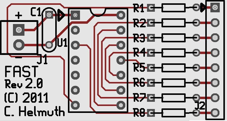
Schematic
FAST Controller

FAST LED Segment
7 LED Segment Board

14 LED Segment Board

Firmware
The firmware is under development. If you are interested in helping add features, please contact chelmuth The current versions are available here.
File:FAST With Tail (Modular Wiring) 20110804.asm
This is the original Static Speed with tail. You can Change the fall rate by changing lines that I have commented.
File:FAST Snowfall Tube With Tail (Random) 20110813 .asm
This is the newer Static Speed and Random Speed firmware. There are more settings you can change in this firmware. Fall Rate, Random Rate, Speed up as it falls, Etc. Looks for the Lines commented with ######## for options you can change to customize your FAST tubes.
The standard code is set up for 56 LED tubes. You only need to change the variables if you are looking for a different length tube, or adjust the parameters of the tubes. There are several variables in this code that may be adjusted:
- The Random Seed for starting the FAST tube, this adjusts the start time of the FAST slightly so multiple FAST tubes look more random together. Look for the following lines near the top of the code :
- endc ;Ends the cblock
- movlw d'2' ;############ CHANGE THIS TO CHANGE THE RANDOM NUMBER SEED #############
- movwf d3 ;Sets D3 Seed
- You can change the '2' to any value 1-8
- To adjust the firmware for different lengths of FAST, look for the following lines near the bottom of the code:
- incf full, 1 ;Was easier than explaining add 1 to LED count.
- movlw d'56'
- movwf fall_count ;######## Set number of LEDs attached to controller ie. 3 segments = 21
- You can change the '56' to the number of LEDs you have in your FAST. Only change this one number not the '56' a few lines higher.
- To adjust the fall speed of the FAST, look for the following lines near the bottom of the code:
- goto Start ;d1 Wasn't 0 goto Start(PWM loop)
- movlw d'40' ;Secondary Fall Speed You Can Lower This Number To Speed Up Falls
- movwf d1 ;Move W to D1 Secondary Fall Speed
- You can change the '40' to a higher number to slow down the fall speed. It is the users choice, but 40-90 give a nice range of speeds.
- You can have the FAST speed up as it falls, look for the following lines near the bottom of the code:
- movwf d1 ;Move W to D1 Secondary Fall Speed.
- ;movfw full ;######### UNCOMMENT IF YOU WANT FALL TO SPEED UP AS IT FALLS
- ;addwf d1, 1 ;######### UNCOMMENT IF YOU WANT FALL TO SPEED UP AS IT FALLS
- decfsz d2,1 ;d1 Was 0 decrease d2 if 0 call to
- Remove the ";" from the beginning of both lines of code to have the FAST speed up as it falls.
File:FAST Snowfall Tube Segment (Diag) 20110926.asm
This is a diagnostic firmware for the FAST. This will go through and light one LED at a time for about 2 seconds to help identify wiring issues or shorts or opens.
Preconfigured Hex Files
This is a collection of preconfigured HEX files that can be downloaded and programmed into the FAST without changing the parameters. They include a several different parameters for speed, random seed and length.
FAST Discussion Threads
Original Thread
Interest Thread
Group Buy Thread
Video
18" Prototype
Full 56 LED Proof of Concept Design
Multiple Snowfall tubes
FAST Troubleshooting
When a FAST is properly working, the LEDs will light one at a time starting at the controller end and continuing to the far end of the LED Segments. When it reaches the bottom it will then restart at the top again.
There are several issues that can prevent a FAST from working properly. The issues typically can result in no LEDs lighting, LEDs lighting in wrong order, Ghosts (LEDs that light dimly), multiple LEDs lighting at once, one LED not lighting and a combination of all of these problems.
THE MAJORITY OF PROBLEMS WITH FAST ARE RELATED TO SOLDERING ISSUES. Take your time to inspect the PCB under a magnifying glass to review the solder joints on the PCBs to identify issues. You are looking for cold solder joints, unsoldered joints, shorts between adjacent connectors, etc. Often a problematic FAST can be repaired by simply reflowing the solder joints associated with circuit connected to the problematic LEDs.
Initial Checks
- Confirm that you have 5VDC power on the correct input terminals.
- Confirm that you have the PIC oriented correctly with the notch towards the top.
- Confirm that you have programmed the PIC with the firmware.
- Confirm that the LEDs are all oriented correctly according to the directions above
- Confirm that all legs of all LEDS are soldered.
- Confirm that all interconnects between LED Segment boards are soldered on both sides.
- Confirm that the LED Segment boards are connected from Output on one board to Input of the next board.
- Confirm that the wiring between the FAST Controller and the first LED Segment Board is wired correctly according to the directions above.
- Inspect all solder joints for shorts to adjacent components.
Diagnostic Firmware
It is very helpful to program the Diagnostic Firmware into the PIC to help identify problematic LEDs or ghosts. The Diagnostic Firmware slows down the fall to a rate where it is possible to easily identify problem LEDs. After installing the PIC with the Diagnostic Firmware power up the FAST and make note of the problem LEDs location (count from the top) and problem.
Wiring Connections
Each LED has 4 legs that must be soldered. When viewed from the top of the circuit board (component side):
The 2 Cathode legs are on the Left side of the LED.
The 2 Anode legs are on the Right side of the LED.
The following wiring diagrams trace the power to the LEDs from the controller board. Because the LEDs are Charlieplexed, the LEDs are connected in numerous ways to the 8 power lines. Each LED is activated when the correct combinations of power and ground are applied to each LED by the Controller.
There are two types of LED Segment PCBs, a 7 LED Segement Board (from the 2011 group buy) and a 14 LED Segment Board (from the 2012 group buy). Use the correct tables to help identify the proper wiring for your FAST. The Pin numbers listed in the rows of the tables refer to the Pins at the various interconnects between the LED Segment boards. The LED connections are listed by LED number (starting from the controller end) and an "A" or "C" reflecting the Anode and Cathode connections to that LED.
7 LED Segment Boards
| LED Segment Board | Controller Board Output Pin 1 | Controller Board Output Pin 2 | Controller Board Output Pin 3 | Controller Board Output Pin 4 | Controller Board Output Pin 5 | Controller Board Output Pin 6 | Controller Board Output Pin 7 | Controller Board Output Pin 8 |
|---|---|---|---|---|---|---|---|---|
| Segment#1 Input | PIN1 | PIN2 | PIN3 | PIN4 | PIN5 | PIN6 | PIN7 | PIN8 |
| Segment#1 | LED7-C | LED6-C | LED5-C | LED4-C | LED3-C | LED2-C | LED1-C | LED1-A, LED2-A, LED3-A, LED4-A, LED5-A, LED6-A, LED7-A |
| Segment#1 Output / Segment#2 Input | PIN2 | PIN3 | PIN4 | PIN5 | PIN6 | PIN7 | PIN8 | PIN1 |
| Segment#2 | LED13-C | LED12-C | LED11-C | LED10-C | LED9-C | LED8-C | LED8-A, LED9-A, LED10-A, LED11-A, LED12-A, LED13-A, LED14-A | LED14-C |
| Segment#2 Output / Segment#3 Input | PIN3 | PIN4 | PIN5 | PIN6 | PIN7 | PIN8 | PIN1 | PIN2 |
| Segment#3 | LED19-C | LED18-C | LED17-C | LED16-C | LED15-C | LED15-A, LED16-A, LED17-A, LED18-A, LED19-A, LED20-A, LED21-A | LED21-C | LED20-C |
| Segment#3 Output / Segment#4 Input | PIN4 | PIN5 | PIN6 | PIN7 | PIN8 | PIN1 | PIN2 | PIN3 |
| Segment#4 | LED25-C | LED24-C | LED23-C | LED22-C | LED22-A, LED23-A, LED24-A, LED25-A, LED26-A, LED27-A, LED28-A | LED28-C | LED27-C | LED26-C |
| Segment#4 Output / Segment#5 Input | PIN5 | PIN6 | PIN7 | PIN8 | PIN1 | PIN2 | PIN3 | PIN4 |
| Segment#5 | LED31-C | LED30-C | LED29-C | LED29-A, LED30-A, LED31-A, LED32-A, LED33-A, LED34-A, LED35-A | LED35-C | LED34-C | LED33-C | LED32-C |
| Segment#5 Output / Segment#6 Input | PIN6 | PIN7 | PIN8 | PIN1 | PIN2 | PIN3 | PIN4 | PIN5 |
| Segment#6 | LED37-C | LED36-C | LED36-A, LED37-A, LED38-A, LED39-A, LED40A, LED41-A, LED42-A | LED42-C | LED41-C | LED40-C | LED39-C | LED38-C |
| Segment#6 Output / Segment#7 Input | PIN7 | PIN8 | PIN1 | PIN2 | PIN3 | PIN4 | PIN5 | PIN6 |
| Segment#7 | LED43-C | LED43-A, LED44-A, LED45-A, LED46-A, LED47-A, LED48-A, LED49-A | LED49-C | LED48-C | LED47-C | LED46-C | LED45-C | LED44-C |
| Segment#7 Output / Segment#8 Input | PIN8 | PIN1 | PIN2 | PIN3 | PIN4 | PIN5 | PIN6 | PIN7 |
| Segment#8 | LED50-A, LED51-A, LED52-A, LED53-A, LED54-A, LED55-A, LED56-A | LED56-C | LED55-C | LED54-C | LED53-C | LED52-C | LED51-C | LED50-C |
| Segment#8 Output | PIN1 | PIN2 | PIN3 | PIN4 | PIN5 | PIN6 | PIN7 | PIN8 |
14 LED Segment Boards
| LED Segment Board | Controller Board Output Pin 1 | Controller Board Output Pin 2 | Controller Board Output Pin 3 | Controller Board Output Pin 4 | Controller Board Output Pin 5 | Controller Board Output Pin 6 | Controller Board Output Pin 7 | Controller Board Output Pin 8 |
|---|---|---|---|---|---|---|---|---|
| Segment#1 Input | PIN1 | PIN2 | PIN3 | PIN4 | PIN5 | PIN6 | PIN7 | PIN8 |
| Segment#1 | LED7-C, LED13-C | LED6-C, LED12-C | LED5-C, LED11-C | LED4-C, LED10-C | LED3-C, LED9-C | LED2-C, LED8-C | LED1-C, LED8-A, LED9-A, LED10-A, LED11-A, LED12-A, LED13-A, LED14-A | LED1-A, LED2-A, LED3-A, LED4-A, LED5-A, LED6-A, LED7-A, LED14-C |
| Segment#1 Output / Segment#2 Input | PIN3 | PIN4 | PIN5 | PIN6 | PIN7 | PIN8 | PIN1 | PIN2 |
| Segment#2 | LED19-C, LED25-C | LED18-C, LED24-C | LED17-C, LED23-C | LED16-C, LED22-C | LED15-C, LED22-A, LED23-A, LED24-A, LED25-A, LED26-A, LED27-A, LED28-A | LED15-A, LED16-A, LED17-A, LED18-A, LED19-A, LED20-A, LED21-A, LED28-C | LED21-C, LED27-C | LED20-C, LED26-C |
| Segment#2 Output / Segment#3 Input | PIN5 | PIN6 | PIN7 | PIN8 | PIN1 | PIN2 | PIN3 | PIN4 |
| Segment#3 | LED31-C, LED37-C | LED30-C, LED36-C | LED29-C, LED36-A, LED37-A, LED38-A, LED39-A, LED40A, LED41-A, LED42-A | LED29-A, LED30-A, LED31-A, LED32-A, LED33-A, LED34-A, LED35-A, LED42-C | LED35-C, LED41-C | LED34-C, LED40-C | LED33-C, LED39-C | LED32-C, LED38-C |
| Segment#3 Output / Segment#4 Input | PIN7 | PIN8 | PIN1 | PIN2 | PIN3 | PIN4 | PIN5 | PIN6 |
| Segment#4 | LED43-C, LED50-A, LED51-A, LED52-A, LED53-A, LED54-A, LED55-A, LED56-A | LED43-A, LED44-A, LED45-A, LED46-A, LED47-A, LED48-A, LED49-A, LED56-C | LED49-C, LED55-C | LED48-C, LED54-C | LED47-C, LED53-C | LED46-C, LED52-C | LED45-C, LED51-C | LED44-C, LED50-C |
| Segment#4 Output | PIN1 | PIN2 | PIN3 | PIN4 | PIN5 | PIN6 | PIN7 | PIN8 |